| Electrical Communication is a free textbook on the basics of communication technology. See the editorial for more information.... |

|
Home  Electrical Fundamentals of Communication Shielding Electrical Fundamentals of Communication Shielding |
|||||||||


|
  |
||||||||
ShieldingIf instruments, or circuits such as bridges, are operated in weak constant electric or magnetic fields, difficulties are seldom experienced. If these fields are strong, however, or if they are alternating rather than constant, then serious troubles are experienced. A circuit or an instrument can be shielded from the effect of a constant (direct) electric field by enclosing the object to be shielded in a metal box.20 Since the metal is electrically conducting, the lines of electric force do not penetrate to the interior but terminate on surface charges. An instrument or circuit can be shielded from the effects of a constant magnetic field by entirely enclosing the device in a thick case of good magnetic material such as iron. The magnetic lines of force follow through the metal of the shield and penetrate less within.
Although shielding against stray alternating-current fields is in reality a process of shielding against electromagnetic waves, it is convenient to consider the separate components.21 There are, therefore, two problems: first, shielding against stray alternating magnetic fields; and second, shielding against stray alternating electric fields. Shielding against stray alternating magnetic fields22 is usually limited to wound apparatus such as transformers. Often the coils are wound on a closed core of some good magnetic material such as iron or Permalloy; then the flux will be confined almost entirely to the magnetic core, and but little coupling to other circuits will be experienced. If such closed cores are not sufficient or are not used, there are two other methods of shielding. The first of these is to enclose the device in a case of magnetic material as previously explained. This shield will prevent the magnetic lines of force from leaving the vicinity of the coil being shielded, and from coupling with another unit. The second method of magnetic shielding is to enclose the device in a box of non-magnetic material, such as copper, having high electrical conductivity. Then the alternating magnetic field produces eddy currents in the copper, and the magnetic field produced by these currents reacts with, and largely neutralizes, the stray field from the device tending to cause interference. Such shields cause losses and change the electrical characteristics of the apparatus shielded. A metal box will shield against stray alternating electric fields. If it is desired to shield the individual pieces of equipment in a network (such as an impedance bridge) from the mutual effects of the other pieces, the problem becomes more difficult. Shielding against an electric field does not consist of preventing mutual coupling, but of controlling the coupling. Two problems are involved, depending on whether the units are in series or in parallel. To illustrate the action of a shield, consider the impedance unit of Fig. 27(a). When an alternating electromotive force is applied between A-B, in addition to the current from A to B through the impedance, current flows from A to B through the stray capacitances and the grounded path as shown by the arrow. These stray capacitances and the resulting currents vary for every different position of the impedance with respect to ground, and with respect to surrounding objects such as an observer. If, however, a conducting shield is placed completely around the impedance as in Fig. 27(b), the stray paths will be made definite, and the impedance between the points A-B will be independent of the location of the unit. Stray capacitance will also exist as shown between the shield and ground, but, since all parts of the shield are at the same potential, no current will flow.
Suppose that two elements are connected in series and that it is desired to shield these from each other, and also so that their impedances are independent of their position with respect to ground and surrounding objects. It might at first appear that connecting them as in Fig. 28(a) would be satisfactory. It is not, however; the two shields are at different potentials, and current will flow as indicated by the arrow. The impedance between A-C will therefore be variable. If, however, the shield is extended as shown in Fig. 28(b), then the stray capacitances between the two shields, indicated by the dotted condenser Cs, will be constant, and the impedance between A-C will be independent of location. This arrangement can be extended to include any number of elements, three elements being shielded in Fig. 28 (c).
Attention is called to the fact that, although shielding tends to make a unit independent of position, it increases the impedance variations with frequency. Thus, if the unit of Fig. 27 (a) is a resistor, the actual circuit between the terminals A-B consists of resistance and capacitance in parallel. This assumes, of course, that the inductance of the resistor is negligible. When the shield is placed in position, the capacitance is increased. Even at voice frequencies the circuit A-B would not be strictly pure resistance, and the higher the frequency, the greater is the deviation from this ideal. Shielding, therefore, does not prevent stray fields and capacitive coupling, but controls these, making them independent of position.
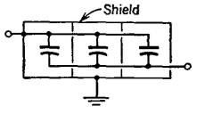
Units connected in parallel should be individually shielded, and all the shields connected to some common point which is then usually grounded. This method is illustrated by Fig. 29.
|
|||||||||
| Home Electrical Fundamentals of Communication Shielding |
|
||||||||


Last Update: 2011-05-14