| Electrical Communication is a free textbook on the basics of communication technology. See the editorial for more information.... |

|
Home  Electroacoustic Devices Telephone Transmitter Operation in Resistive Circuits Electroacoustic Devices Telephone Transmitter Operation in Resistive Circuits |
|||||


|
  |
||||
Telephone Transmitter Operation in Resistive CircuitsIn this section the theory of a single-button, carbon-granule transmitter in a circuit containing resistance only will be discussed. It is assumed that the transmitter diaphragm is excited by a pure tone; also, that the diaphragm of the transmitter and the resistance of the carbon granules vary harmonically. The total resistance at any instant of the circuit of Fig. 4 is
In this expression, Rt is the steady-state transmitter resistance, Rc is the resistance of the remaining portion of the circuit, and r is the maximum variation in transmitter resistance from Rt. When the
sound-wave pressure is maximum, the diaphragm will be pressed in and the circuit resistance will be (Rc + Rt) - r. When the soundwave pressure is least, the transmitter diaphragm will be bent out and the circuit resistance will be increased to the value (Rc + Rt) + r. The current through the transmitter at any instant will be similar to that shown by Fig. 5. It consists of direct and alternating components and is given by the relation
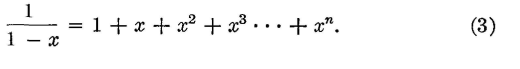
This equation is in the form of the series
Equation 2 may be expanded according to this series, becoming
This equation indicates that, in addition to current variations having the same frequency as the impinging sound waves
harmonics, such as obtained when
is expanded. are produced. These harmonics were not present in the original variations assumed, and thus distortion has been produced, although it is usually not serious. In fact, all terms higher than the first may usually be neglected, and the total instantaneous transmitter current can be written
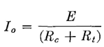
or
where I0 is the normal or steady-state current flowing when the diaphragm is at rest. This equation becomes
From a telephone standpoint, interest is in the largest value that the alternating component may have, that is, in the portion
Since
> the maximum value of the alternating component becomes, from equation 7,
To illustrate the application of this equation, suppose that a number of transmitters of different normal resistance Rt are available for connection to a circuit of resistance Rc, and also assume that for each one the ratio r/Rt = p is a constant value. That is, the percentage change of resistance r when excited by the same source is the same. Then, equation 8 becomes
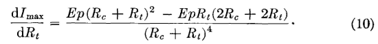
Now let it be assumed that all the factors in this equation are constant except Rt and that the expression is differentiated with respect to Rt. Then,
The greatest value of the alternating component Imax will be obtained if equation 10 is equated to zero. Thus, and
For the maximum useful alternating (speech) component of current in a circuit the steady-state resistance of the transmitter Rt should equal the resistance of the external circuit. If these relations are obtained, the useful output can be increased by substituting a transmitter having a greater change in resistance r.
|
|||||
| Home Electroacoustic Devices Telephone Transmitter Operation in Resistive Circuits |
|
||||


Last Update: 2011-05-18