| Electrical Communication is a free textbook on the basics of communication technology. See the editorial for more information.... |

|
Home  Electric Networks Pads and Attenuators Electric Networks Pads and Attenuators |
|||||


|
  |
||||
Pads and AttenuatorsIt is often desired in communication circuits to reduce the amplitude of a signal wave. For example, the program signal delivered over a telephone line may be transmitted at a power level sufficient to "override" line noise (Chapter 14). A pad, defined1 as "a non-adjustable transducer for reducing the amplitude
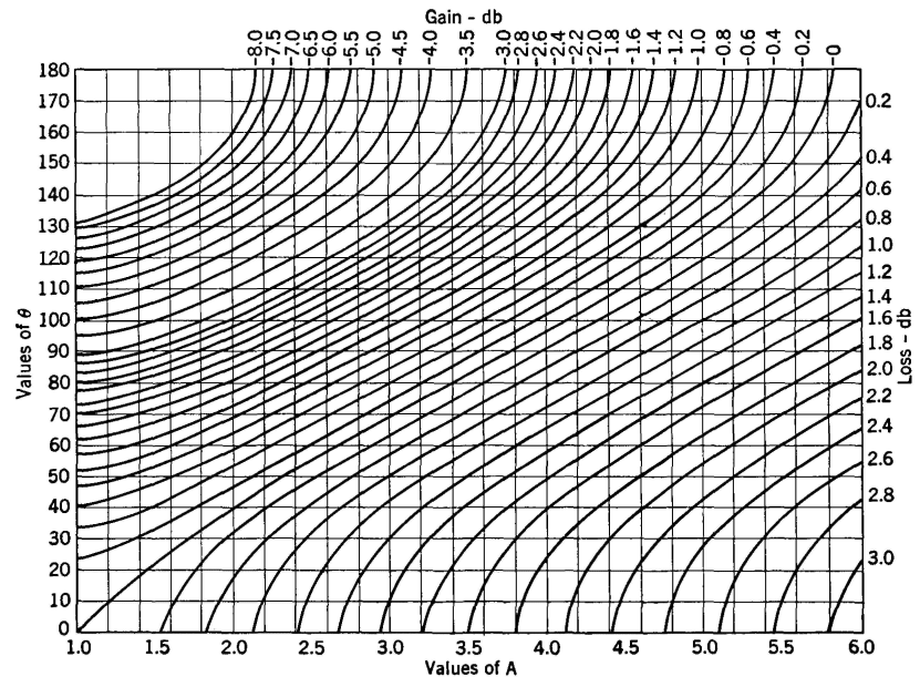
Notes: Values of the reflection loss for any two impedances Zx and Zy are here given as a function of the ratio
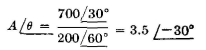
where A is the ratio of the magnitudes and θ is the difference between the angles of the two impedances. The ratio is always to be taken by dividing the larger impedance by the smaller, i.e., so that A will not be less than unity. It is immaterial whether θ is positive or negative. Negative values of reflection losses are reflection gains. Examples: (1) Find reflection loss for the impedances 200/60° and 700/30°
Reflection loss = 1.4 db. (2) Find reflection loss for the impedances 400/35° and 680/45°
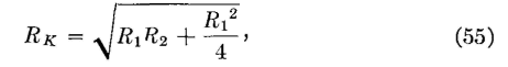
Reflection loss = -1.8 db, (a gain) of a wave without introducing appreciable distortion," may be necessary at the receiving end of the line to reduce the signal volume to the desired amount. An attenuator, defined1 as an "adjustable transducer for reducing the amplitude of a wave without introducing appreciable distortion," is used in radio speech-input equipment to vary the volume of the program signal. Pads are made of fixed resistors and will function over a wide frequency range, determined by the high-frequency characteristics of the resistors. Pads are commonly made in the form shown in Fig. 22, particularly if they are to be used with balanced circuits. In the design of pads, the facts known are usually the impedances of the devices with which the pad is to be associated and the loss in decibels that the pad is to have. In accordance with the theory on page 156, the iterative impedance of the pad of Fig. 22 is
the letter RK being used because the iterative impedance wall be resistance. The power loss in decibels introduced by the pad can be found from power, voltage, or current ratios. If a voltage E12 is impressed at the sending end, the input current will be I12 = E12/RK, because the pad is symmetrical and is terminated in RK. The voltage across the junctions x-y will be
The current through RK will be Exy/(0.5R1 + RK), and this current multiplied by RK will give the output voltage E34 across RK. Thus, and
As an illustration of the use of this equation, suppose that a pad such as Fig. 22 is to introduce a loss of 10 decibels and must have an iterative impedance of 600 ohms. The voltage ratio E12/E34 = 100.05x10 = 3.162, and, from equation 56a, the value of R1 will be 622.5 ohms. With RK and R1 both known, from equation 55 R2 = 422 ohms. Thus the pad of Fig. 22 should be composed of four 156-ohm resistors, and one 422-ohm resistor. Sometimes unsymmetrical taper pads6 having different image impedances are used between circuits of different iterative impedances. Attenuators are made of variable resistors, usually arranged so that they are varied by a common knob. An attenuator of the configuration shown in Fig. 22 is a symmetrical, balanced device. The various resistances that an attenuator must have can be calculated as just explained for each different attenuator setting in decibels. Or calculations can be made at several settings, and curves can be plotted from which the values at other settings can be obtained. An unbalanced pad commonly used is shown in Fig. 23a. This pad also can be designed as just explained. The L-section attenuator of Fig. 23(b) is widely used in unbalanced circuits where the input and the output impedances offered by the attenuator need not remain fixed. This is an unsymmetrical device, but it is satisfactory for many purposes. Equations for the design of this attenuator can be derived in the same way as for the symmetrical pad.
|
|||||
| Home Electric Networks Pads and Attenuators |
|
||||


Last Update: 2011-05-30