| Electrical Communication is a free textbook on the basics of communication technology. See the editorial for more information.... |

|
Home  Electric Networks Electric Transducers Electric Networks Electric Transducers |
|||||||


|
  |
||||||
Electric TransducersMany electric networks, and particularly those considered in this chapter, are electric transducers, defined1 as "an electric network by means of which energy may flow from one or more transmission systems to one or more other transmission systems." An electric transducer generally has four terminals - two input terminals and two output terminals.1 As for any electric network, electric transducers may be either active or passive. Those considered in this chapter are passive; that is, they contain within themselves no source of energy.
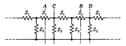
Balanced and Unbalanced Transducers. Most electric networks can be classified as two types on the basis of the arrangement of the impedance elements with respect to ground. The first type is the balanced network of Fig. 2. Assuming that the plane of the network is parallel to the ground plane, that the physical sizes of the Zs elements are the same and that the physical sizes of the Zs' elements are the same, the stray capacitances Cg to ground will be the same. If, also, the impedances of the series elements Zs are identical, and the impedances Zs' are identical, currents I will be the same and the currents IL will be the same. The series elements Zs and Zs' on each side of the circuit are paralleled by the stray capacitances to ground, and the current flowing through the load* is the sum of the currents IL and ICg arriving by the two paths. If the identities previously discussed are maintained then the series voltage drops IZS will be the same: the series voltage drops ILZS' will be the same; and the currents ICg will be the same. Then, the currents I in impedances Zs will be identical, and the currents IL in impedances ZS' will be identical. An unbalanced network is shown in Fig. 3; this is an extreme instance, the series impedances having been omitted in one side. The current that reaches ZL will be IL and ICg much as before, but the current path back to the source has been altered. Thus, I and I' are not equal, and IL and IL' are not equal. A circuit such as Fig. 2 (containing four series elements) will be unbalanced if corresponding series elements Zs are not identical, if corresponding series elements Zs' are not identical, or if the plane of the circuit is not parallel to the ground plane. From the preceding discussion it follows that a balanced network is one in which the corresponding series impedance elements are identical, and one in which these elements are symmetrical (electrically) with respect to some reference (ground) potential. Unbalanced networks are those that do not fulfill these requirements. The ground plane referred to may be the surface of the earth (as for an open-wire transmission line), may be the metal chassis of an amplifier, or may be a metal sheet under the top of a laboratory test bench. If it is necessary to "ground" a balanced circuit such as Fig. 2, the ground wire should be attached at the center of the parallel impedance Zp; this maintains the balance to ground. An unbalanced circuit such as Fig. 3 is often grounded by attaching the ground wire to the side containing no series impedances. Whether a circuit should be balanced or unbalanced and whether it should be grounded or ungrounded depend on circumstances. The important points at present are that fundamentally they are different types of circuits and that in general balanced and unbalanced circuits must not be interconnected for testing or for operation, unless the connection is made through a transformer that has a grounded shield between the primary and the secondary. If this is not done, measurements and operation at communication frequencies (including audio frequencies) will probably be unsatisfactory. By definition,1 the word load means the power that an apparatus or machine delivers. Hence, strictly speaking the word "loading impedance" should be used in Fig. 2 and elsewhere in this book. It is accepted practice in communication to refer to the loading impedance as the load. Because one side of the circuit contains essentially no impedance, it is possible to have one input and one output terminal common. Thus, Fig. 3 is sometimes referred to as a three-terminal network, and Fig. 2 is sometimes referred to as a four-terminal network. This classification is of little (if any) fundamental importance, but whether or not a circuit is balanced or unbalanced is of great fundamental importance.
Symmetrical and Unsymmetrical Transducers. In discussing the network of Fig. 2 it was pointed out that for balance the two Zs elements must be identical, and the two ZS' elements must be identical. For this network to be both balanced and symmetrical, each of the series elements must be identical. If this is true, then the network of Fig. 2 offers the same input impedance characteristics when considered from terminals 1-2 or terminals 3-4.
A network may be unbalanced, yet symmetrical. Thus in Fig. 3, if Zs is of the same impedance as ZS', then the unbalanced circuit will be symmetrical. The network (only) will offer the same input impedance characteristics when considered from terminals 1-2 or terminals 3-4 (see also page 154).
|
|||||||
| Home Electric Networks Electric Transducers |
|
||||||


Last Update: 2011-05-30