| Electrical Communication is a free textbook on the basics of communication technology. See the editorial for more information.... |
|
Home  Transmission Lines Constants of Open-Wire Lines at Radio Frequencies Transmission Lines Constants of Open-Wire Lines at Radio Frequencies |
|||


|
  |
||
Constants of Open-Wire Lines at Radio Frequencies
Open-wire lines15, 16, 17 are used in radio for connecting the radio transmitter to
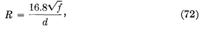
the sending antenna and for similar purposes. It is assumed that the conductors are of hard-drawn copper. Series Resistance R. The resistance at radio frequencies of both wires of a transmission line is
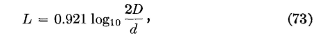
where f is the frequency in cycles per second, d is the diameter of the wires in centimeters, and R is in microhms per meter of line. The resistance can also be found by the method of page 215. Series Inductance L. The series self-inductance at radio frequencies of both wires of a transmission line is
where D is the distance between the wires, d is the diameter of the wires in the same units as D, and L is in microhenrys per meter of line. Shunt Capacitance C. The shunt capacitance between the two wires of a radio-frequency transmission line is
where C is the capacitance in microfarads per meter of transmission line and D and d are as previously explained. Equations 73 and 74 do not apply for twisted pairs and are accurate only when D/d is about 10 or more. Shunt Conductance G. Shunt conductance G was discussed on page 219 for an open-wire line at low frequencies. A similar discussion applies at high frequencies, but this constant is usually neglected in radio.
|
|||
| Home Transmission Lines Constants of Open-Wire Lines at Radio Frequencies |
|
||

Last Update: 2011-05-18