| Electrical Communication is a free textbook on the basics of communication technology. See the editorial for more information.... |

|
Home  Transmission Lines Open-Wire Transmission Line at Radio Frequencies Transmission Lines Open-Wire Transmission Line at Radio Frequencies |
|||


|
  |
||
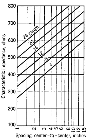
Open-Wire Transmission Line at Radio FrequenciesThe methods of using preceding equations will be considered now. As an illustration a line composed of two No. 4 A.W.G. (diameter, 0.518 centimeter) hard-drawn copper wires spaced 18 inches (45.7 centimeters) apart will be considered at a frequency of 10.0 megacycles and at 20°C. Calculation of Linear Electrical Constants. The series resistance R is, from equation 72, R = 16.8*sqrt(107)/0.518 = 102.5 X 10³ microhms per meter, or 0.1025 ohm per meter. The series inductance L is, from equation 73, L = 0.921 log10 2 X 45.7/0,518 = 2.065 microhenrys per meter. The shunt capacitance C is, from equation 74, C = 0.000012/ lg 2 X 45.7/0.518 = 0.00000534 microfarad per meter. The shunt conductance G is assumed negligible. Calculation of Propagation Constant. Propagation constant may be calculated by equations 37 or 75, or α and β may be evaluated by equations 76 and 77. Using these last two equations, α = (0.1025/2) X sqrt(0.00000534 x 10⁻⁶/2.065 x 10-6) = 8.26 X 10⁻⁵ neper per meter, and β = 6.28 x 10⁷*sqrt(2.065 x 10-6 x 0.00000534 X 10-6) = 0.209 radian per meter. Using the value of Z0 calculated in the next paragraph and the second expression of equation 76, α = 0.1025/2 x 620 = 8.27 x 10⁻⁵ neper per meter. Calculation of Characteristic Impedance. Characteristic impedance may be calculated from equations 50, 79, or 80. Using equation 79, Z0 = sqrt(2.065 x 10⁻⁶/0.00000534 x 10-6) = 620 ohms resistance. Using equation 80, Zo = 276 log10 2 x 45.7/0.518 = 620 ohms resistance. The characteristic impedance of typical radio-frequency transmission lines is given in Fig. 20.
Calculation of Wavelength and Wave Velocity. From equation 54, λ = 6.28/β = 6.28/0.209 = 30 meters (approximately). The wave velocity is, from equation 55, V = ω/β = 6.28 x 10⁷/0.209 = 3 x 10⁸ meters per second. Calculation of Line Performance. The radio-frequency transmission line of the preceding paragraphs is to deliver 10.0 kilowatts of power to an antenna 500 feet (152.5 meters) from the transmitter. The antenna terminates the line so that no standing waves exist. The sending-end conditions are desired. The receiving-end current will be Ir = sqrt(P/R) = sqrt(10000/620) = 4.02 amperes. The receiving-end voltage will be Er = sqrt(PR) = sqrt(10000 x 620) = 2490 volts. The sending-end power will be computed as follows: The loss in the 500-foot (152.5-meter) line was computed to be 8.26 x 10⁻⁵ neper per meter, and hence the total loss will be about 12.6 x 10⁻³ neper. This is 12.6 x 10-3 x 8.686 = 0.1093 decibel. From equation 49, page 86, the power input will be P = 10 x 100.1*0.1093 = 10.255 kilowatts, or 10255 watts. The sending-end current will be Is = sqrt(10255/620) = 4.07 amperes. The sending-end voltage will be Es = sqrt(10255 x 620) = 2525 volts. The efficiency of the radio-frequency transmission line will be 10000/10255 = 97.5 per cent. The preceding calculations neglect the power radiated by the radio-frequency transmission line. These radiation losses can be calculated approximately by the equation15
where P is the radiation loss in watts, I is the line current in amperes, and D is the line spacing and A the wavelength, both in the same units. This equation holds15 if the line is terminated in its characteristic impedance, if the line spacing is less than (0.1λ and if the line length is more than 20D.
|
|||
| Home Transmission Lines Open-Wire Transmission Line at Radio Frequencies |
|
||

Last Update: 2011-05-30