| Electrical Communication is a free textbook on the basics of communication technology. See the editorial for more information.... |

|
Home  Cables and Wave Guides Transmission Equations for Coil-Loaded Circuits Cables and Wave Guides Transmission Equations for Coil-Loaded Circuits |
|||||||


|
  |
||||||
Transmission Equations for Coil-Loaded CircuitsIn practice, loading coils having an impedance of ZL/2 are installed in series with each cable conductor at spacings S miles apart as indicated in Fig. 7. A section of this loaded circuit may be represented by the network of Fig. 8, where the part A-B, C-D is the equivalent T section of the section of cable S (without the loading) having a characteristic impedance Z0 and propagation constant γ per mile.
It is seen from Fig. 8 that the characteristics of the final loaded cable are a combination of the section A-B, C-D having distributed constants and the lumped loading coils ZL/2 at each end. The propagation constant γL and the characteristic impedance Z0L of the final
loaded cable may be considered the propagation constant and the characteristic impedance of an exactly equivalent uniform cable represented diagrammatically by the T section of Fig. 9. Adding the loading coils to the circuit does not appreciably change the shunt paths of Figs. 8 and 9. It can therefore be written that
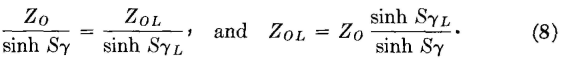
Again referring to these figures, it is seen that
Then,
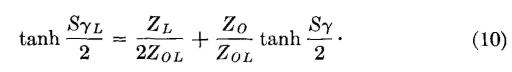
When the value of ZOL given by equation 8 is substituted in equation 10,
and
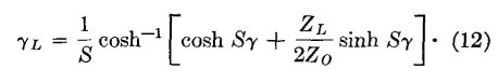
This is the Campbell formula5 for a loaded cable, giving the propagation constant γL of the loaded cable in terms of the values of the unloaded cable and the impedance of the loading coils. Considerable mathematical reduction is required between equations 10 and 11; this will be found on page 181 of reference 6. As shown in reference 6, equation 11 can be written (since cosh2 x = sinh2x + 1),
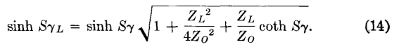
and this can be reduced to the form
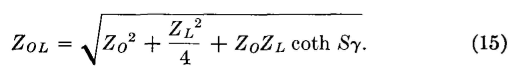
When equation 14 is substituted in equation 8, it follows that
This formula gives the mid-load or mid-coil characteristic impedance of the lump-loaded cable in terms of the constants of the cable, before loading, and the impedance of the loading coils. A similar equation can be derived for the midsection termination.
|
|||||||
| Home Cables and Wave Guides Transmission Equations for Coil-Loaded Circuits |
|
||||||


Last Update: 2011-05-30