| Electrical Communication is a free textbook on the basics of communication technology. See the editorial for more information.... |

|

Home  Cables and Wave Guides Cables and Wave Guides  The Location of Impedance Irregularities The Location of Impedance Irregularities |
|||||


|
|||||
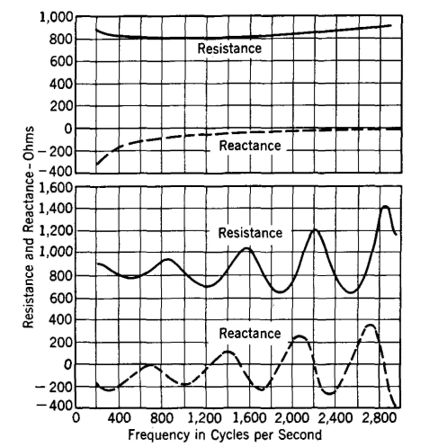
The Location of Impedance IrregularitiesIn loading cable circuits it is possible to reverse the loading coil connections and install the coil so that the magnetic effects oppose, and thus the coil will have an incorrect inductance. Such a discontinuity and other impedance irregularities in a line or cable (such as those caused by high-resistance joints, defective loading coils, or transposition errors in open wire and splicing errors in cables) cause wave reflections, and thus the measured impedance characteristics of a circuit may vary as in Fig. 21. Such irregularities interfere with telephone operation if they do not altogether prevent it.
It will be observed that cable irregularity causes periodic variations in both the resistance and the reactance components. It is possible from such curves to locate line impedance irregularities. When an electromagnetic wave strikes an impedance irregularity, part of the wave is reflected. The magnitude of the reflected wave depends on the nature of the unbalance existing. When this reflected wave reaches the sending end, it may either aid or oppose the current entering the line (depending on the frequency and distance to the unbalance) and thus makes the measured sending-end impedance (Z = E/I) either higher or lower as Fig. 22 indicates. If the distance to the irregularity is great and the velocity of propagation is low, many reflected wavelengths will be included, and hence only a small frequency change is required to add another wavelength between the source and the irregularity. The equation for determining the distance to the irregularity can be derived by referring to Fig. 22. In this figure the reflected current subtracts from the current which would exist if the line were smooth (that is, had no irregularity), and thus the sending current is smaller
and the impedance Z = E/I is maximum. If now the frequency is increased so that, instead of two and one-quarter waves, two and three-quarters waves are included in the distance d, the same reflected current phase relations and a second maximum impedance value will be obtained. Where f1 and λ1 are the frequency and wavelength for the first condition, and n is the number of wavelengths included, it can be written that the distance d to the irregularity is
Similarly, for the second condition it can be written that
The value n = d/λ1 obtained from equation 22 can be substituted in equation 23, which then becomes
If V is the velocity of propagation in the circuit, then λ = V/f, and equation 24 becomes
This may be written
where d is the distance to the irregularity in miles, when V is the velocity of propagation in the circuit in miles per second, and fl and f2 are the frequencies between which impedance peaks occur as in Fig. 21. The velocity of propagation of the cable of Fig. 21 is about 19,570 miles per second at 1000 cycles. The length between impedance peaks at about this frequency is approximately 650 cycles. Thus from equation 26, d = 19570/(2 x 650) = 15.05 miles (approximately). That is, the irregularity causing the reflections is located about 15 miles from the testing end. During such tests it is, of course, necessary to have the distant end of the line terminated in the line characteristic impedance so that reflections will not be caused at this point.
|
|||||
Home  Cables and Wave Guides Cables and Wave Guides  The Location of Impedance Irregularities The Location of Impedance Irregularities |
|||||
Last Update: 2011-05-30


