| Electrical Communication is a free textbook on the basics of communication technology. See the editorial for more information.... |

|
Home  Electronic Applications in Communication Basic Rectifier Circuits Electronic Applications in Communication Basic Rectifier Circuits |
|||


|
  |
||
Basic Rectifier CircuitsHalf-Wave Rectifier. A half-wave rectifier circuit is shown in Fig. 9. Appreciable current flows through the rectifier element only in the direction of the arrow. The sine-wave voltage a, when impressed on the rectifier and load in series, will produce a half-wave current through the load resistor RL and a half-wave voltage across load resistance RL, as shown by curve b. If the rectifiers are assumed to be ideal, the equation for this half-wave voltage is
If the terms e and Em are changed to i and Im, then the equation for the rectified current results. The first term is the desired rectified direct-current component c; the second term is a component d having the same frequency as the source; the third term is a second harmonic e having a frequency twice that of the source; and the fourth term is a fourth harmonic f having a frequency four times that of the source. These separate components are plotted in Fig. 9, and, if they are combined, as by adding at the broken lines, Fig. 9(b) results. Full-Wave Rectifier. A sine-wave voltage a will produce a full wave such as shown by b of Fig. 10. The equation for the rectified full-wave voltage across the load is
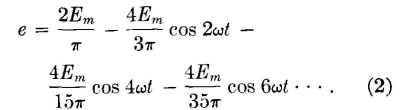
This equation can also be used to represent the rectified current. The first term is the desired rectified direct-current component. The other terms are the second, fourth, and sixth harmonics; other harmonics are neglected. These components can be represented in the same manner as in Fig. 9 and then can be combined to give the wave of Fig. 10(b). Polyphase Rectifiers. When a large amount of power, perhaps a kilowatt or more, is to be rectified, polyphase rectifiers are used.
Three-phase rectifiers are often used with large radio transmitters,8 and rectifiers of greater numbers of phases are commonly used in large industrial installations.9 Bridge Rectifiers, A full-wave bridge rectifier is shown in Fig. 11. For either direction of the applied alternating voltage, current will flow through the resistor as shown. The transformer may be omitted if desired.
|
|||
| Home Electronic Applications in Communication Basic Rectifier Circuits |
|
||


Last Update: 2011-05-18