| Electrical Communication is a free textbook on the basics of communication technology. See the editorial for more information.... |

|
Home  Electronic Applications in Communication Cutout in Rectifier Filters Electronic Applications in Communication Cutout in Rectifier Filters |
|||||


|
  |
||||
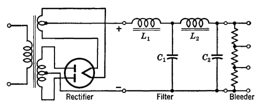
Cutout in Rectifier FiltersThe preceding section implied that, if an inductor were placed next to the rectifier, choke-input filter operation resulted and that, if a capacitor were placed next to the rectifier, condenser-input filter operation resulted. This depends on the magnitude of the inductor and capacitor, and on the resistance of the load.10 For example, if the load is drawing a large direct current, a filter connected as in Fig. 12 may operate as a choke-input filter and the direct voltage will be essentially as given by the first term of equation 2. But, if the same circuit is supplying a small value of direct current to the load, the same filter may then operate as a condenser-input filter. When a rectifier, filter, and load are so related that filter operation is like that with condenser input, the capacitor (even though there may be an inductor between it and the rectifier) draws a high peak current and it charges almost to the peak of the rectified voltage wave; then cutout occurs. At this point, the rectifier current falls to zero, and the capacitor maintains the voltage across the filter and load. As a comparison, the voltages across the two types of filters are shown in Fig. 13. It is apparent that the average, or direct, voltage of Fig. 13 (a) with choke input is less than in Fig 13(6) for condenser input. If for any condition of operation, cutout occurs, then the voltage across the load will rise, and the regulation1 will be poor. If certain assumptions are made,12 it can be shown that for cutout not to occur, the relation
must apply. In this equation, L1 is the minimum value of inductance in henrys that the first inductor must have, and RL is the resistance in ohms of the load. It is common practice13 to use 1000 instead of 1130 in equation 3. A resistor, called a bleeder, is often connected permanently across the filter output (Fig. 14). If this bleeder has the correct value given by equation 3, it will prevent cutout. Such a bleeder may be provided with taps, and then it serves as a voltage divider. A permanently connected bleeder ensures that the capacitors discharge when the rectifier is deenergized, and the bleeder may prevent injuries to operating personnel.
|
|||||
| Home Electronic Applications in Communication Cutout in Rectifier Filters |
|
||||

Last Update: 2011-05-30