| Electrical Communication is a free textbook on the basics of communication technology. See the editorial for more information.... |

|
Home  Electronic Applications in Communication Equivalent Circuit of a Vacuum Tube Electronic Applications in Communication Equivalent Circuit of a Vacuum Tube |
|||


|
  |
||
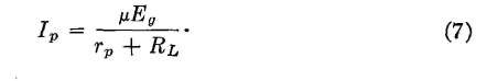
Equivalent Circuit of a Vacuum TubeWhen used as a non-distorting amplifier, the signal voltage to be amplified is impressed between the grid and the cathode, and these signal voltage variations cause corresponding signal-current flow in the plate circuit. Because the grid voltage is more effective than the plate voltage in controlling plate-current flow, the equivalent circuit of a vacuum tube16 as an amplifier is shown in Fig. 17. The alternating signal current that flows through the load resistor is
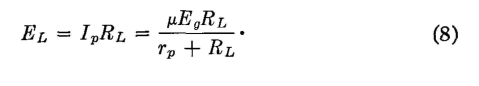
The signal voltage across RL is
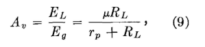
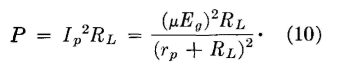
which may be expressed in decibels if desired. The power delivered to the load resistor RL is
|
|||
| Home Electronic Applications in Communication Equivalent Circuit of a Vacuum Tube |
|
||

Last Update: 2011-05-18