| Electrical Communication is a free textbook on the basics of communication technology. See the editorial for more information.... |

|
Home  Electronic Applications in Communication Amplifiers Characteristics of Resistance- Coupled Amplifiers Electronic Applications in Communication Amplifiers Characteristics of Resistance- Coupled Amplifiers |
|||||


|
  |
||||
Characteristics of Resistance-Coupled AmplifiersA voltage amplifier must not produce appreciable distortion (page 85). If the tubes are operated correctly, as shown in Fig. 20, the non-linear distortion is negligible. The frequency response (and frequency distortion) is affected greatly by the circuit constants as will now be explained.
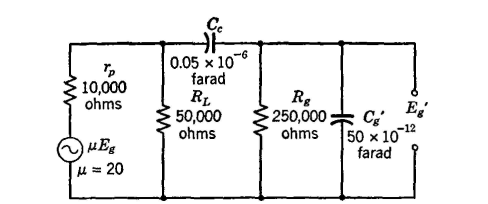
The equivalent circuit of one stage of a resistance-coupled amplifier is shown in Fig. 21. The condenser Cg' is the sum of the wiring capacitance Cw and the equivalent grid input capacitance Cg of the second tube, given by the equation12
In this expression Cgk is the grid-to-cathode capacitance and Cgp is the grid-to-plate capacitance of the tube, and Av is the voltage gain per stage. This equation applies to triodes only. For tetrodes and pentodes Cg' is the sum of the wiring capacitance and the grid input capacitance which is given in vacuum-tube manuals. Gain at Intermediate Audio Frequencies. From the values given in Fig. 19 and assuming that Cg' is about 50 micromicrofarads, at an intermediate frequency of 1000 cycles, the effects of Cc and Cg' are negligible. Then, from equation 9, Av = (20 x 41,700)7(10,000 + 41,700) = 16.1. The value of RL used in this equation is the equivalent resistance of RL and Rg of Fig. 21 in parallel, or (50,000 x 250,000)/(50,000 + 250,000) = 41,700 ohms. At this frequency the circuit is resistance only, and there is no phase shift except as discussed in connection with Fig. 18.
Gain at Low Audio Frequencies. At low frequencies, such as 50 cycles, the effect of Cg' of Fig. 21 becomes negligible, but Cc must be considered. The frequency at which the gain is 3 decibels below the intermediate audio frequency and the phase shift caused by the circuit is 45° is
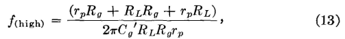
where f is in cycles, Cc is in farads, and the resistances are in ohms. Gain at High Audio Frequencies. At high frequencies, such as 20,000 cycles, the effect of Cc of Fig. 21 becomes negligible but Cg' must be considered. The frequency at which the gain is 3 decibels below the intermediate audio frequency and the phase shift caused by the circuit is 45° is
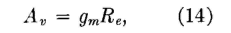
where f is in cycles, Cg' is in farads, and the resistances are in ohms. Theory alone predicts that RL and Rg of Figs. 19 and 21 should be very high so that the alternating current will be low, the internal voltage drop caused by the plate resistance will be low, and most of the available voltage μEg will appear across the output terminals. Because the direct-current component must flow through RL, it is impractical to make RL more than three to five times rp this rule applying only to triodes. For triodes, Rs is from about 250,000 to 1,000,000 ohms. For tetrodes and pentodes, the plate resistances are so high that this rule cannot be followed, and typical values of RL are from 250,000 to 500,000 ohms, with values of Rg about the same as for triodes. The equations that have been used were derived12 using Thévenin's theorem (page 148). Because of the very high internal plate resistance of a pentode (usually over 1,000,000 ohms) and the relatively low load resistance used, equations can be derived using Norton's theorem (page 149). Thus the gain at intermediate frequency is
where Re is the equivalent parallel resistance of rp, RL, and Rff. Often the effect of rp is neglected because it is so high, and Re is assumed to equal the parallel resistance of RL and Rg. This assumption should not be made with triodes and equation 14 should not be used with triodes.
|
|||||
| Home Electronic Applications in Communication Amplifiers Characteristics of Resistance- Coupled Amplifiers |
|
||||


Last Update: 2011-05-18