| Electrical Communication is a free textbook on the basics of communication technology. See the editorial for more information.... |

|
Home  Electronic Applications in Communication Amplifiers Audio-Frequency Class A1 Single Triode Power Amplifier Electronic Applications in Communication Amplifiers Audio-Frequency Class A1 Single Triode Power Amplifier |
|||||


|
  |
||||
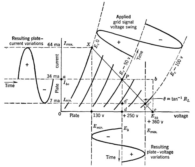
Audio-Frequency Class A1 Single Triode Power AmplifierThe simplified circuit of an audio-frequency power amplifier is shown in Fig. 23. The input impedance of the loudspeaker or other device is transformed into the correct value (page 292) and appears between points 1-2 in series with the tube. Assuming that the load is pure resistance and that the transformer is perfect, then the impedance between points 1-2 will be a pure resistance RL. The power delivered to the load impedance is given approximately by equation 10. A convenient method of analysis19 for a single triode power amplifier is shown in Fig. 24. The direct plate voltage Eb is first selected at some convenient value. The correct grid voltage to use is approximately
The selected plate voltage and the calculated grid voltage establish the operating point P. The line X-Y is the load line and is drawn
through the selected point of operation P at the angle, made with the vertical, θ = tan-1RL. It will be noted that in this figure the abscissas are in volts, the ordinates, in milliamperes, and RL,in ohms. For Fig. 24, the grid bias Ec = -50 volts, the plate voltage Eb = +250 volts, and the load resistance is RL = 3900 ohms, the grid is driven to zero value, and the plate-voltage and grid-current values are as shown. For a single tube such as in Fig. 23, the power output is
and the percentage second harmonic distortion is
Second harmonic distortion = The plate-circuit efficiency, or ratio of signal power output to direct power input, is low for this amplifier. For maximum power output, the load resistance should equal the plate resistance (page 152). Because of second harmonic distortion, caused by the curvature of the dynamic characteristic curve of a triode, the relation just mentioned cannot be used. Experience has shown that for maximum "undistorted" power output the load resistance should be about twice the plate resistance. As used here, "undistorted" means that the nonlinear distortion is less than about 5 per cent. The dynamic curve mentioned is the curve for the tube and its load resistance. This curve can be obtained experimentally or can be calculated.16 It corresponds to the load line of Fig. 24.
|
|||||
| Home Electronic Applications in Communication Amplifiers Audio-Frequency Class A1 Single Triode Power Amplifier |
|
||||


Last Update: 2011-05-30