| Electrical Communication is a free textbook on the basics of communication technology. See the editorial for more information.... |

|

Home  Electronic Applications in Communication Electronic Applications in Communication  Oscillators Oscillators  Velocity-Modulated Oscillators Velocity-Modulated Oscillators |
|||


|
|||
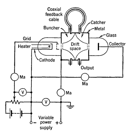
Velocity-Modulated OscillatorsThe diagram of Fig. 40 is of an early velocity-modulated tube called a Klystron. Electrons from the cathode are accelerated by the positive grid and are formed into wrhat may be termed a beam, The electrons that do not strike the grid are further accelerated toward the grid-like structure of the buncher cavity. Some electrons are abstracted from the beam by the buncher electrodes, and others pass on to the catcher, where again some are abstracted, and the remainder flow on to the collector and back to the cathode. Because a beam of electrons is more or less random in nature, some natural grouping of electrons will occur, for fast electrons will overtake slow ones. These clusters of electrons will induce voltages and currents in the cavities. This action can be explained as follows: When a group of negative electrons in the electron beam approaches the first grid of the buncher cavity of Fig. 40, these electrons will repel electrons from the first grid and cause them to flow around the cavity walls to the second grid. As the group of electrons in the beam approaches the second grid of the cavity, these electrons drive electrons out of the second grid, around the walls of the cavity, and back to the first grid. This action causes the two grids to have different electric charges on them and results in a potential difference between them. Currents are caused to flow in the cavity walls. If groups of electrons continue to pass rapidly through the grids at regular intervals, high-frequency alternating voltages and currents will be induced in the buncher cavity. Of course, similar action will occur at the grids of the catcher cavity.
The preceding action was based on random bunching of the electrons. If, now, energy is abstracted from the catcher cavity by a small loop placed at the "short-circuited" end where the current is largest (page 211) and if this energy is fed back through the connecting coaxial cable in the proper phase to excite and drive the buncher cavity, an alternating voltage that will intensify the grouping of electrons in the beam will appear between the buncher grids. This additional bunching will cause an increase in catcher voltages and currents, greater feedback will occur, and the oscillations will build up until an equilibrium condition is reached. The reflex Klystron has a single resonant cavity, and a reflector electrode which is negative with respect to the cathode.36 The electron beam from the cathode is accelerated by the positive grids of the resonator, and some of these electrons flow through the resonator grids and on toward the reflector. The electrons are bunched as they pass through the grids. The negative reflector electrode reflects the elecirons back through the resonator grids, and on this return passage energy is abstracted by the resonator from the electrons. By this feedback method oscillations are sustained. The frequency of the oscillations can be varied by changing the potential of either the accelerating voltage or the reflector voltage. This is called electron tuning. These tubes readily generate waves a few centimeters long. The Klystron can be operated as an amplifier. If the signal to be amplified is injected into the buncher cavity through the coaxial cable and small loop, this signal will cause the electron beam to bunch in accordance with it. When these high-speed electrons have reached the catcher cavity they are well bunched and impart signal energy to the cavity, the energy being abstracted by a loop and coaxial cable. Other Klystron amplifiers are used.33 Sometimes the cavities are separate from the tube.37
|
|||
Home  Electronic Applications in Communication Electronic Applications in Communication  Oscillators Oscillators  Velocity-Modulated Oscillators Velocity-Modulated Oscillators |
|||
Last Update: 2011-05-30


