| Electrical Communication is a free textbook on the basics of communication technology. See the editorial for more information.... |

|
Home  Telegraph Systems Start-Stop Printing Telegraphy Telegraph Systems Start-Stop Printing Telegraphy |
|||||||


|
  |
||||||
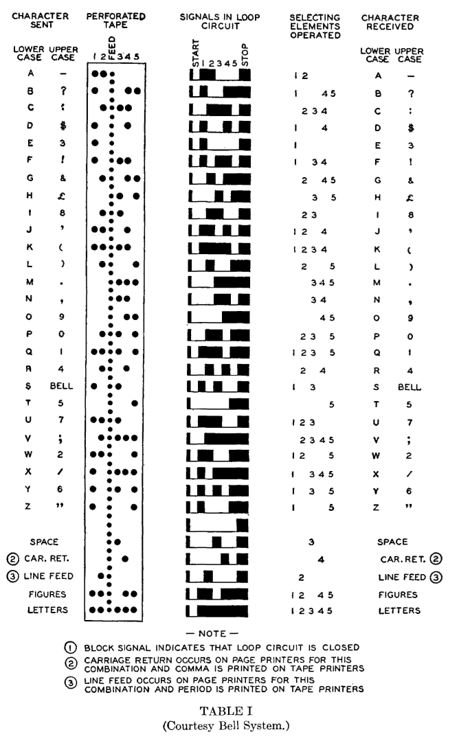
Start-Stop Printing TelegraphyStart-stop printing telegraphy employs an electromechanical device usually called a teletypewriter or teleprinter at the receiving end of the telegraph channel, and often at the transmitting end as well. Other names, such as simplex printer, printer, and teletype, are sometimes used. These instruments are complex in mechanical detail, and only the general features will be presented. Before attempting to explain the start-stop principle, it will be well to consider briefly several possibilities. If a typewriter keyboard were constructed so that when a key is depressed an electrical contact is made, if the printing portion were constructed with an electromagnet operating each printing element, and if one separate line wire were used to connect each sending key with each corresponding printing arm, then a message sent at the keyboard would be printed at the distant station. Such a system would, of course, require so many connecting wires as to be of little commercial value. If a signal code were used, however, the number of wires required could be reduced materially. A number of codes are possible, and the Baudot code shown in Table I has been adopted. Each element of the code is a dot, dashes not being employed. With this code, intelligence could be sent in the following manner: If the letter A were to be sent, keys 1 and 2 of Fig. 12 would be depressed, operating electromagnets 1 and 2 at the distant station. Similarly, if an F were to be sent, keys 1, 3, and 4 would be depressed, operating the corresponding electromagnets at the distant station. This system would have little commercial value.
Suppose that, instead of the five sending keys being connected to the receiving electromagnets by five line wires, they are connected to the segments of distributors and the brush arms are connected by one line wire. If the arms of Fig. 13 are driven in synchronism and if keys 1 and 2 are closed, electromagnets 1 and 2 will be operated because the brushes pass over corresponding segments at the same instant. If these signals are now cleared and keys 1, 2, and 4 are closed, electromagnets 1, 2, and 4 will be operated on the next revolution. Though more elaborate in detail, both the start-stop and the multiplex systems operate on this principle. Several types of distributors have been perfected for sending and receiving the impulses; of these the segmented-ring distributors just described have been widely used.
The elements of the start-stop equipment are shown in Fig. 14. The sending distributor has connections to a set of six transmitter contacts, and the receiving distributor has connections to a set of seven contacts, five of which are connected to the receiving magnets. The keyboard is similar to a typewriter keyboard.
When a key is pressed, it operates the contact mechanism and energizes the proper segments.11 Suppose that it is desired to send the letter A, which consists (Table I) of the first two units. When the A key is depressed segments 1 and 2 will be connected to the transmitter bus by a notched-bar arrangement. At the same time the start magnet is energized, releasing the sending brush arm which is driven by an electric motor. When the arm passes segment 7, a spacing impulse is sent out on the line to the distant receiving teletypewriter, releasing the line relay armature and operating the receiving start magnet which in turn releases the motor-driven receiving brush arm. The two arms revolve at about the same speed, and, when the sending arm passes over segment 1, which is energized, an impulse is sent over the line to segment 1 of the receiving distributor, which in turn operates the connected receiving magnet. Similarly, when the sending arm passes over energized segment 2, an impulse is sent receiving magnet 2. The remaining segments 3, 4, and 5 are not energized, and thus no impulses are sent. When the sending brush moves on segment 6 a marking signal is sent, holding the receiving start magnet circuit open and the receiving arm in readiness for the next letter combination. The sending arm is also held for the next letter. The signals received by the magnets operate an arrangement of code selector bars which in turn permit the printing of the letter received. Modern teletypewriters11, 12 operate on this basic principle just explained but differ in detail. In particular, a revolving-cam arrangement is used instead of the revolving brush and distributor of Fig. 14. Also, one receiving magnet, instead of five, is used.13 Two types of start-stop teletypewriters are available, the tape printer and the page printer.11,12 In the former the received message is printed on a narrow gummed paper strip which can be pasted on the message blanks. In the latter, it is printed on a page, and carbon copies may be made if desired.
|
|||||||
| Home Telegraph Systems Start-Stop Printing Telegraphy |
|
||||||


Last Update: 2011-05-30