| Electrical Communication is a free textbook on the basics of communication technology. See the editorial for more information.... |

|

Home  Telegraph Systems Telegraph Systems  Carrier Telegraph Systems Carrier Telegraph Systems |
|||||||


|
|||||||
Carrier Telegraph SystemsCarrier systems are used by both the Bell System (page 411) and Western Union to increase the message handling capacity of transmission circuits. Two basic methods are used, amplitude-modulated carrier systems and frequency-modulated carrier systems. Because both modulation and carrier systems will be considered in detail in Chapter 11, the present treatment of carrier telegraph systems will be condensed. Amplitude-Modulated Carrier Telegraph Systems.15,16,33-37 A different carrier frequency, higher than the usual telegraph frequencies, is assigned to each incoming telegraph channel from printing telegraph equipment. In effect, carrier-frequency energy is caused to flow on the line to the distant receiving station in accordance with the incoming telegraph signals. Many such channels, each employing a carrier of different frequency, are connected in parallel to the telegraph line which usually is a two-wire, or metallic, circuit that is designed to transmit the carrier-telegraph signals. Because the amplitude of the carrier wave is controlled or modulated by the incoming telegraph signals from the teletypewriters, the term amplitude modulation is used. Sometimes this is termed on-off modulation. At the receiving station the high-frequency signals are demodulated by suitable rectifying equipment, and the resulting current impulses are used to operate the connected printing equipment.
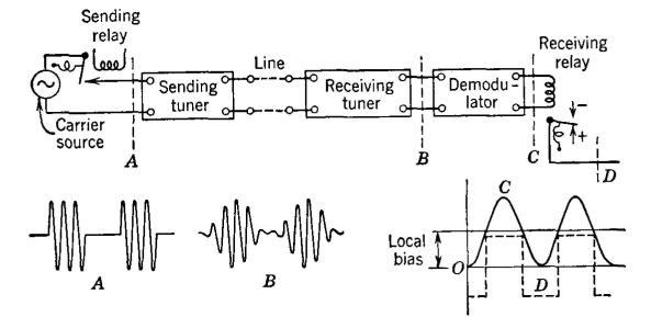
The details of the several carrier telegraph systems vary, but the basic idea is shown in Fig. 17 which is for one carrier channel. The incoming impulses from the sending telegraph equipment cause the sending relay to connect the carrier source and transmit carrier impulses, such as in A, into the sending tuner. This "smooths out" the impulse by removing undesired high-frequency harmonics (see also page 318) and impresses an impulse such as B on the line, together with other such impulses from other channels. The receiving tuner, or filter, tuned to a particular channel frequency, receives an impulse somewhat as shown at B, and, when this is rectified, signals shaped like C result. These cause relay operation D, which in turn operates the printing equipment. Other channels are connected in parallel and the signals are separated from each other by the tuners or filters. About 1,700,000 miles of carrier telegraph channels are provided in the Bell System alone. It should be mentioned that many carrier-telegraph channels can be operated over one telephone channel. Carrier telegraph systems have been classified as high-frequency telegraph systems,34 and as voice-frequency telegraph systems.35 Frequency-Modulated Carrier Telegraph Systems.16,37,38 Although amplitude-modulated carrier telegraph systems are used by both the Bell System and Western Union, the latter is standardizing on frequency-modulated systems. In these, the "carrier frequency" at which the channel operates is caused to move down 70 cycles by a marking signal, and to move up 70 cycles by a spacing signal. For this reason the terms frequency-shift modulation and F - S modulation are sometimes used.
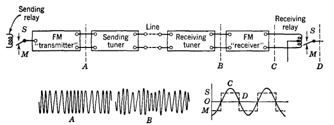
A block diagram of a typical system is shown in Fig. 18. A sending relay arrangement such as indicated would cause the frequency-modulated signal to have sudden frequency transitions and appear as in A. Electronic control is used, however, and the change in frequency is accomplished gradually. After removing undesired components, the transmitted and the received components are more nearly represented by B. This signal is passed through a limiter, which removes all amplitude variations, and then is demodulated in a discriminator, which gives out impulses such as C. These actuate the receiving relay. The action of the limiter and the discriminator and much information on frequency modulation will be found in Chapter 13. The Western Union has found frequency-modulation systems to be particularly free from interference from all causes.15,37 Typical overall frequency assignments of carrier telegraph systems are shown in Fig. 19. The manner in which one system is further broken down into individual telegraph message channels is explained in reference 15. By 1947 Western Union was operating over 500,000 miles of carrier channels. A frequency-modulation telegraph system that does not employ the conventional telegraph relay has been developed.39
|
|||||||
Home  Telegraph Systems Telegraph Systems  Carrier Telegraph Systems Carrier Telegraph Systems |
|||||||
Last Update: 2011-05-30


