| Electrical Communication is a free textbook on the basics of communication technology. See the editorial for more information.... |

|
Home  Telephone Exchange Service and Systems Common-Battery System - Non-Multiple Switchboard Telephone Exchange Service and Systems Common-Battery System - Non-Multiple Switchboard |
||||||||||||||||||||||||||||||||||||||||||||||||||||||||||||||||||||||||||||||||||||||||||||||


|
  |
|||||||||||||||||||||||||||||||||||||||||||||||||||||||||||||||||||||||||||||||||||||||||||||
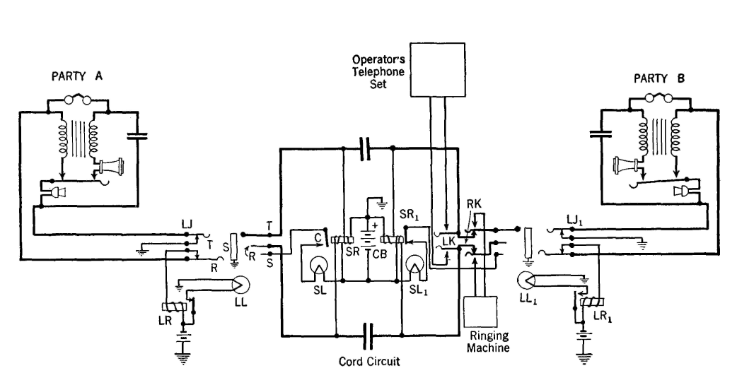
Common-Battery System - Non-Multiple SwitchboardThe common-battery, non-multiple switchboard is suited for either a village or a private branch exchange (P.B.X.) in a large store, hotel, or similar establishment. In this system, the line jacks of each party served by the switchboard are within reach of each operator. The TABLE I PAIRS OF WIRES IN EXCHANGE CABLES
number of lines that can be handled is limited by at least two factors: first, an operator can handle only a certain number of incoming calls per unit of time; and second, an operator can reach only a given switchboard area without moving from her chair. To explain the operation of Fig. 14, suppose that party A wishes to call B. To attract the attention of the operator, A will remove the receiver from the hook, which will close the switch-hook contacts and allow direct current to flow through the line relay LR. When this relay is energized it will pull up the armature closing the path through the line lamp LL and thus signal the operator.
The operator will answer this signal by inserting the answering plug of a cord circuit into the line jack LJ of the calling party which is indicated by the lighted line lamp. The insertion of this plug does three things. First, the contacts will be spread apart, de-energizing the line relay LR, allowing the armature to fall back due to gravity, and thus extinguishing the line lamp. Second, the tip contact T and the ring contact R of the plug will make contact with T and R of the line jack. The closing of these two contacts will permit direct current from the common battery CB to flow out to the calling telephone A. The path of, this current will be from the positive battery (grounded) terminal through one half of the inductive supervisory relay SR to the tip of the plug, then, through the telephone set, back through the ring of the plug, through the other half of the supervisory relay SR, and to the negative battery terminal. The current through the two halves of the supervisory relay SR will attract the armature, opening the contact C. Third, the sleeve contact S on the plug will touch the ground contact S on the jack. The supervisory lamp SL would now light if the supervisory relay had not previously opened. The circuit of the supervisory lamp is, however, now in a condition to light the lamp as soon as this relay contact closes, as it does in a later operation. The operator then throws the listening key LK to the listening position. This closes the contacts at the key and connects the operator's telephone set across the line. The desired number is obtained from the calling party, and, if the called line is not busy, the operator inserts the plug of the calling cord corresponding to the answering cord previously used into the line jack of the called party. When this plug is inserted, the contacts of the line jack LJ1 are opened, and therefore when the receiver of the called party B is removed from the hook the line lamp LL1 does not light. The insertion of the plug does, however, light the supervisory lamp SL1 through the grounded battery and ground on the sleeve. It should be remembered that the receiver at B is still on the hook and that no current is flowing through SR1 to hold open the armature contact of this relay. The operator now throws the ringing key RK to the ringing position. This action connects the called line to the ringing supply and opens the contacts to the line of the calling party so that the calling party will not receive the unpleasant ringing current. The operator will continue to ring until the called party responds. When the called party B removes the receiver from the hook, the contacts at the receiver are closed and current from the battery flows out to the called set B through the two halves of the supervisory relay SR1. This current pulls up the armature of this relay, thus opening the contact and extinguishing the supervisory lamp SL1, indicating to the operator that called the party has answered and that ringing may be discontinued. The two parties A and B then converse. Attention is called to the fact that all the switchboard lamps associated with this switchboard circuit are dark when conversation is in progress. When A and B have completed their conversation they replace the receivers on the hooks. This opens the receiver-hook contacts at both of the sets and breaks the path of the currents through SR and SR1, respectively. The armatures of these relays drop back, closing the associated contacts and permitting current to flow through each of the lamps SL and SL1. The lighting of these lamps indicates to the operator that the conversation is completed, and the connection is accordingly cleared by removing each plug from the jack. After the conversation the operator can be called by slowly moving the receiver hook up and down, causing the supervisory lamps SR or SR1 to flash if the connection has not been cleared, or causing the line lamp to flash if the connection has been removed.
|
||||||||||||||||||||||||||||||||||||||||||||||||||||||||||||||||||||||||||||||||||||||||||||||
| Home Telephone Exchange Service and Systems Common-Battery System - Non-Multiple Switchboard |
|
|||||||||||||||||||||||||||||||||||||||||||||||||||||||||||||||||||||||||||||||||||||||||||||
Last Update: 2011-05-30