| Electrical Communication is a free textbook on the basics of communication technology. See the editorial for more information.... |

|
Home  Telephone Toll Service and Systems The 21-Type Repeater Telephone Toll Service and Systems The 21-Type Repeater |
|||


|
  |
||
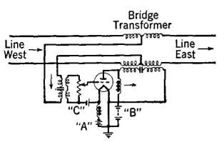
The 21-Type RepeaterThe circuit of this repeater, shown in Fig. 7, is fundamentally the arrangement of Fig. 6. To explain the operation of this circuit, assume that a voice-frequency signal comes in from line west. If the impedances of the input and the output circuits are equal, the incoming energy will divide, half being dissipated in the output circuit and the other half being introduced into the input circuit where it is amplified. This amplified power is again introduced on the line, where it divides, one half flowing west where the speaker hears his voice as an echo, and the other half flowing to the listener on the east line.
The 21-type repeater12,15 is very simple in operation, requires but a small amount of equipment, is relatively cheap to install and operate, but is limited in application. To prevent oscillations, or singing,1 the impedance of line west must equal that of line east, for, as the preceding section shows, if these relations do not hold the output and the input circuits will be coupled. Because the 21-type repeater sends amplified energy in both directions, the repeater is not suited for tandem operation (several repeaters installed at different points in the same line) because the energy flowing back toward the speaker (and toward the listener) would be ream-plified and reintroduced in both directions on the line at each repeater point, causing bothersome echoes.
|
|||
| Home Telephone Toll Service and Systems The 21-Type Repeater |
|
||
Last Update: 2011-05-30