| Electrical Communication is a free textbook on the basics of communication technology. See the editorial for more information.... |

|
Home  Telephone Toll Service and Systems Balancing Networks Telephone Toll Service and Systems Balancing Networks |
|||||


|
  |
||||
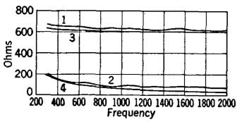
Balancing NetworksAs explained on page 404, the impedance offered by a line or cable connected to a hybrid coil in a telephone repeater must be balanced by the impedance of a network also connected to the hybrid coil. For the usual open-wire telephone line, the impedance offered to the hybrid coil will be approximately the characteristic impedance of the line, For a loaded cable, the impedance offered to the hybrid coil will depend on the type of cable, type of loading, and the terminating sections used (page 248). Impedance variations for an open-wire telephone line composed of 165-mil hard-drawn copper wires spaced one foot apart are shown in Fig. 13. Curve 1 is the resistive component of the input impedance, and curve 2 is the capacitive reactance component of the input impedance, with the distant end properly terminated.12 Theoretically, these curves should be perfectly smooth, but small irregularities cause minor reflections and introduce the small impedance variations.
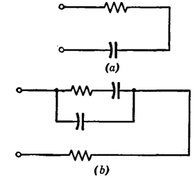
It is evident that the resistance component is by far the larger of the two, and hence the line could be approximately balanced with a 600-ohm resistor. Accurate balancing, such as in repeater circuits, demands a closer simulation, and this can be accomplished by adding a capacitor in series with the resistor as is done in Fig. 14(a). The network can be made to balance the line more exactly by adding another capacitor and another resistor as in Fig. 14(b). The curves for this final balancing network are numbers 3 and 4 of Fig. 13, and as is evident they closely balance the line impedance over a wide range of frequencies. The balancing networks just described simulate the impedance of an open-wire line. Balancing networks23, 24 are also needed for use in repeaters connected to loaded cables.
|
|||||
| Home Telephone Toll Service and Systems Balancing Networks |
|
||||
Last Update: 2011-05-30