| Electrical Communication is a free textbook on the basics of communication technology. See the editorial for more information.... |

|
Home  Radio Systems The Demodulation of Frequency- Modulated Waves Radio Systems The Demodulation of Frequency- Modulated Waves |
|||||


|
  |
||||
The Demodulation of Frequency-Modulated WavesSeveral systems have been developed. Two methods that are successfully employed will be discussed. The Limiter and Discriminator.2 The limiter is a device that "clips off" the received and amplified frequency-modulated signal so that no amplitude variations (such as might be caused by static) occur in the wave envelope. Several types of limiters are used, singly or in combination; among these are the crystal detector (page 272), circuits using vacuum tubes that limit because of grid-current flow through a resistor, and circuits using tuned amplifiers that saturate because of low plate voltage.43 Because it removes unwanted amplitude variations, the limiter is very important. The discriminator is the demodulating device that is actuated by the frequency-modulated radio signal and produces a replica of the original modulating signal. The discriminator is an outgrowth of frequency-control methods.44,45 Modifications of the discriminator circuit of Fig. 26 are used. The operation of the discriminator when the received signal is at midfrequency is as follows: After passing through the limiter, the radio-frequency signal that is frequency modulated is impressed as indicated in Fig. 26. The primary is tuned to the midfrequency, and, if at the instant under consideration the frequency is at midfrequency, the vector diagram at the left in (6) applies. The impressed voltage Ep causes the 90° lagging current (approximately) to flow in the primary coil. This current induces a 90° lagging voltage Ei in series in the secondary coil that also is tuned to the midfrequency. The secondary current IS will be in phase with this voltage when the signal is at midfrequency. A voltage drop will be caused across the secondary capacitor, and this will lag the secondary current by 90°. The connections are assumed to be such that the voltage between the anode and the cathode of each tube is the vector sum of the primary voltage Ep and one-half of the secondary voltage Es The capacitor connecting the primary and the center of the secondary is sufficiently large to have negligible reactance. When the signal is at midfrequency E1 and E2 are equal, the rectified currents I1 and I2 are equal, and, since R1 equals R2, no resultant voltage will exist at the audio-output terminals. The operation of the discriminator when the received signal is below midfrequency is as follows: For this frequency the secondary will be out of resonance, capacitive reactance will predominate, Is will lead Ei, and the secondary voltage Es will be as indicated. This causes diode voltage E1 to exceed diode voltage E2, rectified current I1 will exceed
I2, and, since R1 equals R2, the lower audio-output terminal will be positive and the upper terminal will be negative. The operation of the discriminator when the received signal is above midfrequency is as follows: The secondary will be out of resonance for this frequency and inductive reactance will predominate, causing the secondary current Is to lag the voltage Ei. This results in diode voltage E2 exceeding E1; also, rectified current I2 will exceed I1, and the upper audio-output terminal will be positive and the lower negative. At the frequency-modulation transmitter, one cycle of modulating audio signal voltage causes a frequency shift below midfrequency and a shift above midfrequency. This will cause one cycle of audio-output discriminator voltage. At the transmitter a strong modulating voltage will cause a large frequency shift, and, at the receiver, a large frequency shift will result in a greater lead, or lag, and a stronger audio output. In some circuits the capacitor connecting the primary and the secondary of Fig. 26 is omitted, and a coil is placed in the wire leading to the center of the secondary. This coil is coupled to the primary and serves to pick up a reference voltage that corresponds to EP of Fig. 26(b) and (c). The discriminator is satisfactory, particularly if it is modified as just explained, but it must be preceded by a limiter. Because the limiter reduces the signal to the point at which all normal amplitude variations are eliminated, the intermediate-frequency amplifier preceding the limiter must have much gain; also, two limiter stages are sometimes used for more complete limiting action. The Ratio Detector. The ratio-detector of Fig. 27 requires no limiter. Note that one diode is reversed and that other significant changes have been made from Fig. 26. Also, the capacitor between primary and secondary is usually omitted, and, as for some discriminators, another secondary coil is placed in series with the ware to the center of the secondary.50 The vector diagrams of Fig. 26 apply to the ratio detector.
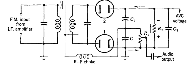
Capacitor C3 of Fig. 27 is often about 8 microfarads, and the circuit is such that the voltage across C3 can vary only slowly. Assume that a station is unmodulated and is, accordingly, on center frequency. If the station produces a strong signal (the limiter is omitted when a ratio detector is used), a large rectified current will flow as shown by the arrows, and capacitor C3 will charge slowly to a relatively large voltage value. If the station produces a weak signal, a small rectified current will flow and capacitor C3 will discharge slowly to a low value. This makes available an automatic volume-control voltage between the terminal AVC and ground. Note that at the center frequency no current flows through the R-F choke or resistor R1. If the transmitter is frequency modulated and the signal falls below the center frequency, the radio-frequency voltage across diode 1 will increase and that across diode 2 will decrease (Fig. 27). This will cause the current in diode 2 to fall and that in diode 1 to rise; this causes flow through the R-F choke and through resistor R1. The voltage across capacitor C2 will fall, and that across C1 will rise, but the sum of these voltages will equal that across C3. When the frequency rises above the midfrequency, the action is reversed. Thus, an audio voltage, which corresponds to the frequency shifts in the received-modulated signal, exists across resistor R1. If a sudden change occurs in the magnitude of the received frequency-modulated signal, the magnitude of the demodulated output voltage remains fixed because capacitor C3 holds the voltage constant across capacitors C1 and C2. Only the ratio of these voltages can change. Thus a limiter need not be used.
|
|||||
| Home Radio Systems The Demodulation of Frequency- Modulated Waves |
|
||||

Last Update: 2011-05-30