| Electrical Communication is a free textbook on the basics of communication technology. See the editorial for more information.... |

|
Home  Radio Systems Radio-Relay Systems Radio Systems Radio-Relay Systems |
|||||||


|
  |
||||||
Radio-Relay SystemsSince the beginning of electrical communication, efforts have been directed toward increasing the number of messages transmitted from point to point over one two-wire circuit. These efforts have resulted in the coaxial cable that will pass as many as 600 telephone messages simultaneously. With the development of radio, attention was given to the development of point-to-point radio-relay systems that would each pass a large number of messages. Coaxial cables and radio-relay systems are in economic competition. The United States is now (1949) spanned with a coaxial system, and installation of a transcontinental point-to-point radio relay system is in progress. These systems may be used either for telephone purposes or for television. Radio-relay systems operate at superhigh frequencies, using wavelengths of approximately 10 centimeters. They use small amounts of power and highly directional antennas that are of the electromagnetic horn,56 parabolic,57 or lens58 types. The antennas are mounted on tall buildings,, towers, and hills. Surprising as it may seem, such systems have been used for some time, the first probably being a two-way channel installed in 1931 across the straits of Dover and using Barkhausen, or positive-grid, oscillators, page 306, at approximately 1725 megacycles and a wavelength of 17.4 centimeters.59 Recent literature on point-to-point radio relay systems has been extensive.60,61,62,63,64 In the paragraphs immediately following, the New York-Boston radio relay system will be described briefly. Two basic types of equipment are required: the terminal equipment,64 by means of which the messages or television programs to be transmitted are translated to the superhigh frequency region, and the micro-wave repeaters,62 which receive the complex signal after it has traveled about 30 miles, amplify the signal, and direct it on to the next relay repeater station.
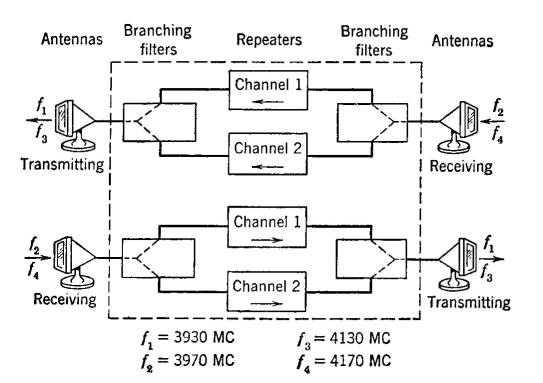
The New York-Boston system operates at about 4000 megacycles (wavelength about 7.5 centimeters). Two two-way channels are provided, each capable of handling a television program extending from 30 cycles to 4.5 megacycles; or, the system can be used to transmit hundreds of telephone messages furnished by a type L carrier system (page 432). The average length of the repeater sections is 27.5 miles, 35 miles being the longest. At the input terminal equipment, the incoming signal is frequency modulated and emerges at a 65-megacyele center frequency. By modulation methods, this is raised to 3930 megacycles, is amplified, and passes through waveguides to the transmitting antenna, which is a metallic lens in the mouth of an electromagnetic horn. Parallel strips of metal of various dimensions act as waveguides and produce a focusing effect. At the receiving terminal the process is reversed. At the repeater stations, shown in block form in Fig. 30, the signal is received by an antenna as previously described, is reduced to an "intermediate frequency" of 65 megacycles, is amplified, then translated to about 4000 megacycles, is amplified in a "radiofrequency" amplifier, and finally is retransmitted to the next station using the same type antenna. These translations are necessary because the velocity-modulated amplifying tubes (page 306) for low-level amplification at 4000 megacycles proved to be too noisy. Conventional tubes are used for low-level amplification at 65 megacycles, and velocity-modulated tubes (page 308) are used for high-level amplification at 4000 megacycles,62 In the New York-Chicago link of the transcontinental radio-relay system, and in similar installations, special high-frequency triodes instead of velocity-modulated tubes are used.(1) The system just described is operated by the Bell System. Another point-to-point microwave relay system is operated by Western Union over a triangle connecting New York, Pittsburgh, and Washington. Frequencies of about 4000 megacycles are used. Klystrons that are frequency modulated are used to drive small dipole antennas with parabolic reflectors. The Klystron is frequency modulated by a resultant signal composed of many telegraph messages. The power output of the Klystron is about 100 milliwatts. A detailed description of the system is given in Western Union Technical Review, July, 1948, Vol. 2, No. 3.
|
|||||||
| Home Radio Systems Radio-Relay Systems |
|
||||||
Last Update: 2011-05-30