| Electrical Communication is a free textbook on the basics of communication technology. See the editorial for more information.... |

|
Home  Radio Systems Television Radio Systems Television |
|||


|
  |
||
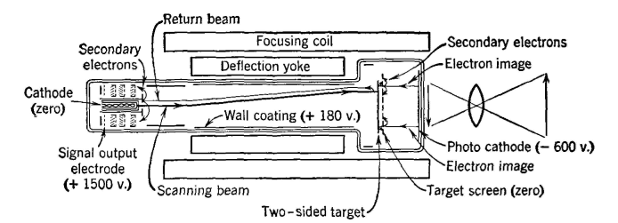
TelevisionExperimental work on television has been in progress for many years. A two-way television system74 that transmitted over wire telephone circuits was operated for some months about 1930, and at approximately the same time television in colors was also demonstrated.75 During the years following these experiments, television has been the subject of much research, and several successful methods have been developed. Television shows great promise, and there are some who predict that television is destined to capture the present radio-broadcast audience, particularly in city and suburban areas. This remains for the future to disclose. The Image Orthicon, Much of the success of television is due to the development of the Image Orthicon76 by the Radio Corporation of America. A simplified schematic diagram of the Image Orthicon is shown in Fig. 32. The light reflected by the object or scene to be televised is
focused on the photocathode, which throws off electrons, forming an "electron image" of the object or scene. The two-sided target and target screen (Fig. 32) are at +600 volts with respect to the photo-cathode, and the electron image travels to the target. The electrons constituting the electron image are maintained in their respective places by the focusing coil that holds them in parallel rays. The two-sided target of Fig. 32 is of low-resistance semiconducting glass. It is so thin that electric charges flow readily through the glass but do not flow "sideways" with ease. The electrons in the electron image striking the glass target knock out secondary electrons, and a positive charge pattern is formed on one side of the glass. This pattern is an electric-charge image of the visible image to be televised. A beam of electrons from an electron gun is directed at the other side of the target, and this beam is caused to move in lines back and forth at various levels (somewhat as the page of a book is read), thus scanning the side of the two-sided target nearest the electron gun. Because the glass conducts from one side to the other, if secondary emission from the "front" side maintains a given area on this side positive, the corresponding area on the "back" side (toward the electron gun) will also be positive. If there is no positive charge on an area being scanned at a given instant, the electrons in the scanning beam will be repelled at that instant. If there is a positive charge on an area scanned; some electrons will be absorbed, and the rest will be repelled. In this way, the electron beam is modulated, or controlled in intensity, corresponding to light reflected by the portion of the image scanned at that instant. The repelled electrons, constituting the modulated current, strike a comparatively large electrode around the aperture of the electron gun from which they are shot. Secondary electrons are produced, and these enter several stages of secondary electron multiplication. The output is the so-called video signal, and this is ready for amplification in wideband amplifiers, and then for radiation by a local television station, or for transmission over a coaxial cable system, or a radio-relay system, to operate some distant television station. The Image Orthicon and associated apparatus constitute the television camera.77 The term video is used, technically, to describe the original signal coming from the television pickup device. There is a tendency to use this term to specify television in general. The video band extends from about 30 to 4,500,000 cycles. Television Transmitters. Television channels are assigned in the very-high-frequency portion of the radio spectrum. For this reason, special tubes and equipment are used.78 Special antennas must be used because of the high frequencies involved, and the wide band to be transmitted.79 Amplitude modulation is used for the video, or picture signal, one sideband is suppressed, and the carrier and other sideband are transmitted. Frequency-modulation is used for the audio signal of the speech or music program accompanying the television image transmission. One important function of the transmitting equipment is the generation and transmission of synchronizing impulses needed for "locking together" the television camera and the television receiver.80 Television Receivers, Television receivers include equipment for demodulating the received television image signals and for reproducing the image on a cathode-ray tube. Also, equipment is included for demodulating the accompanying speech or music signals and for reproducing the program on a loudspeaker. There are circuits for synchronizing the scanning of the electron beam in the cathode-ray tube in the receiver with the electron beam used in scanning in the distant television camera.80 The superheterodyne principle is used in television receivers. As explained, the electron beam in the cathode-ray tube of the television receiving set scans in synchronism with the beam in the camera tube. The intensity of the beam of the cathode-ray tube is varied in accordance with the instantaneous intensity of the current from the television camera tube. In this way, the television image is reproduced on the end of the cathode-ray tube. In some television sets the image is viewed directly as it is reproduced on the end of the tube, and in others it is viewed indirectly by a suitable optical system.81 Special receiving antennas are required.82
|
|||
| Home Radio Systems Television |
|
||
Last Update: 2011-06-05