| Electrical Communication is a free textbook on the basics of communication technology. See the editorial for more information.... |

|
Home  Interference and Noise Methods of Induction Interference and Noise Methods of Induction |
|||||||||||


|
  |
||||||||||
Methods of InductionElectric energy is transferred from power lines into communication circuits and from one communication circuit into another in three ways. First, energy transfer may occur through leakage paths between the two circuits. This is usually of little importance, and its solution is obvious.
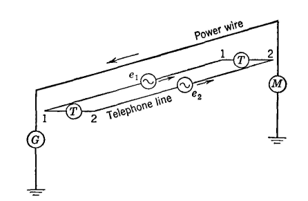
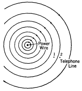
The magnetic field offers the second medium for introducing interfering currents into communication circuits. Thus, in Fig. 1, assume that a grounded alternating-current power line parallels a metallic two-wire telephone line as indicated. The power-line current will then produce a magnetic field about the power wire, and this field will link with the telephone line as shown in Fig. 2. Instantaneous induced voltages, represented by the generators e1 and e2, will be produced in the telephone wires. Since wire 1 is closer to the power line than wire 2, wire 1 will have a greater voltage induced in it by the alternating magnetic field, and thus a difference of potential e1-e2 will exist between wires 1 and 2. This difference of potential (often called metallic-circuit induction, and sometimes transverse induction) will cause a current to flow in the telephone circuit, and noise from the power line will accordingly be heard in the telephone receivers.
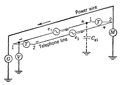
The magnetic field causes a voltage to be induced in series with each wire. As Fig. 3 indicates, one end of each wire is positive and the other is negative. A difference of potential (often called longitudinal-circuit induction) will also exist between the wires and ground. If a high-impedance voltmeter V is connected as in Fig. 3, the voltmeter will deflect because the circuit is completed through the distributed capacitance represented by Cg1.
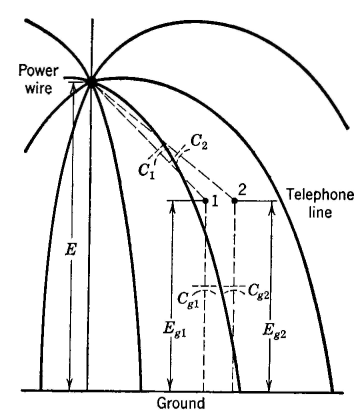
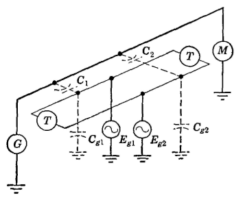
The third method by which noise energy is introduced into paralleling telephone circuits can be explained from a consideration of the power-line voltages and distributed capacitances between the circuits involved (Fig. 4). Considering for the moment one wire only, suppose that C1 represents the distributed capacitance between the power wire and wire 1, and that Cg1 represents the capacitance of wire 1 to ground. The effective voltage E between the power wire and ground will divide inversely proportional to the capacitances, and thus Eg1 = EC1/(C1+C2). The voltage from wire 2 to ground will be less than Eg1 since the respective distances between wires are greater, but the capacitances to ground are the same.
Since the two voltages to ground are unequal, the wires will have a difference of potential between them, and this will cause noise currents to flow through the connected telephone sets. The way in which the two telephone wires are raised to a voltage above ground is also shown in Fig. 5. The induced voltages are represented by the small generators Eg1 and Eg2. From this section it is apparent that the power-line current and the resulting magnetic field induce voltages which act as small generators connected in series in the line wires (Fig. 1). Also, the power-line voltage and the resulting electric field raise the paralleling telephone-line wires to voltages above ground, and these voltages act as small generators connected between the telephone wires and ground (Fig. 5).
In this discussion and the one which follows, it has been assumed that the telephone line is paralleled by a power line consisting of a single grounded wire. Such lines seldom exist for commercial power purposes, but, as will be discussed later, under certain conditions a three-phase power line has the characteristics of a grounded circuit as just considered. Also, the grounded system applies for the single trolley wire of an electric railway.
|
|||||||||||
| Home Interference and Noise Methods of Induction |
|
||||||||||
Last Update: 2011-05-30