| Electrical Communication is a free textbook on the basics of communication technology. See the editorial for more information.... |

|
Home  Interference and Noise Crosstalk Measurements Interference and Noise Crosstalk Measurements |
|||


|
  |
||
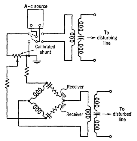
Crosstalk MeasurementsThese measurements are made with a crosstalk meter shown greatly simplified in Fig. 22. A standard interrupted "tone" was formerly used as a source, but now a special warble oscillator is employed.35 The signal is impressed on the disturbing circuit, and the amount transferred by magnetic and electric coupling (and also by leakage) is detected in the receiver connected to the disturbed circuit. This received amount is then compared with the original signal by the switching arrangement shown. When the calibrated shunt is so adjusted that the sound heard through the shunt and that heard over the disturbed line are equally loud, then the setting of the shunt gives the crosstalk. One unit of crosstalk exists between two circuits when the current flowing in the disturbed circuit is one one-millionth of that flowing in the disturbing circuit. The noise meter is often used instead of a receiver for determining when the two sounds are equally loud.
The tests just described are for near-end crosstalk. If the standard source is impressed on the disturbing circuit at the distant end of the line, the measurements are termed far-end crosstalk. Although the tests just described are for crosstalk between metallic circuits, other tests, such as crosstalk from the phantom to side circuits, are also made. Care must be taken to ensure that the circuits are properly terminated when noise and crosstalk tests are made. At the frequencies employed in carrier telephone work (Chapter 11) special crosstalk equipment and measuring methods must be used. Such equipment is described in the literature devoted to carrier systems.36
|
|||
| Home Interference and Noise Crosstalk Measurements |
|
||
Last Update: 2011-05-30