| Electrical Communication is a free textbook on the basics of communication technology. See the editorial for more information.... |

|
Home  Interference and Noise Principles of Plant Protection Interference and Noise Principles of Plant Protection |
|||||


|
  |
||||
Principles of Plant ProtectionCommunication plant, including lines, cables, subscriber equipment, and central-office equipment, must be protected from excessive currents and voltages. The following cover most of the sources of dangerous currents and voltages in communication systems: 1. Lightning and other atmospheric disturbances. 2. Differences in the potential of the earth in different localities caused by earth currents due usually to electric railway or power systems, or to phenomena accompanying the aurora borealis. 3. Physical contact or insulation leaks between power and telephone lines. 4. Induced voltages from power lines usually during abnormal operating conditions. 5. Abnormal conditions such as short circuits in improperly designed central-office equipment, 6. High-power radio transmitting stations. These sources cause three general types of electrical hazards to lines and equipment. The first of these is high voltages. Protection is obtained from these by open-spaced cutouts. The second hazard is heavy currents, and these are protected against by fuses. The third type is currents slightly in excess of the normal operating values. These currents are often called "sneak" currents, and, although they do no harm if they flow for only a short time, the cumulative heat they develop may cause serious damage to apparatus if they flow for a considerable period. Protection is afforded by heat coils.
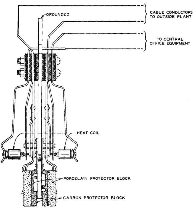
Open-Space Cutouts. In Fig. 23 is shown a carbon protector block upon which a porcelain block is held by a spring. This porcelain block has a small carbon insert which it holds a definite distance from the carbon block, providing an air gap. As can be seen in this drawing, the carbon protector block is at ground potential, and the spring touching the carbon insert is at line potential. If the potential between line and ground exceeds a certain value, the gap sparks across, allowing this potential to disappear. If the sparking is intense, carbon dust from the blocks may put a permanent ground on the wire; and, if the sparking is prolonged, sufficient heat may be generated to soften the cement holding the carbon insert in place, thus allowing the spring to push the insert against the carbon block. This action places a permanent ground on the line. The average cutout used at stations and central offices breaks down at 350 volts. Those used at the junctions of open wire and cable average 710 volts. Open-space cutouts often become dirty after they have been discharged many times and place high resistance unbalances on the lines, tending to cause the lines to become noisy. Insulating transformers are used in extreme cases to isolate equipment from lines exposed to dangerous potentials, such as when telephone wires are placed on power-transmission poles. Drainage coils are sometimes used to protect telephone lines against lightning.37 Fuses. The fuses usually employed blow if the current exceeds about 7 amperes. Fuses are used in conjunction with open-space cutouts and are placed on the line side. If the cutout grounds the system, a heavy current often flows; and if the fuses are on the line side, this current will operate the fuses and will not damage the telephone circuits. One factor in the selection of 7 amperes as the current limit for the fuse is that it is desired that the fuse will carry the 6.6 amperes used in series street-lighting systems without blowing. In such series circuits a very high voltage tends to build up across a gap. If such a circuit comes in contact with a telephone line and is grounded through the open-space cutout and fuse, operation of the fuse might cause the voltage of the series circuit to increase, as a result of which the arc across the fuse is maintained, causing a fire hazard. Heat Coils. A heat coil consists essentially of a coil of fine wire wound on a copper tube into which a pin is soldered. The heat coil is held in position, as shown in Fig. 23, by a spring, and, when the heat becomes sufficient to melt the solder, the spring forces the pin through the tube until the pin encounters a ground plate, thus grounding the circuit. A typical heat coil will carry 0.35 ampere for 3 hours but will operate in 210 seconds on 0.54 ampere. A typical installation38 of these protective devices (on one wire) is shown in Fig. 24. Strange as it may seem at first, buried toll cables of both the conventional type and the coaxial type sometimes must be protected against lightning.39,40 Of course this would be unnecessary if the earth were a perfect conductor. It is of interest to note that underground cables are injured sometimes by gophers.41
|
|||||
| Home Interference and Noise Principles of Plant Protection |
|
||||

Last Update: 2011-05-30