| Basic Radio is a free introductory textbook on electronics based on tubes. See the editorial for more information.... |

|
Home  Some Special Circuits Pulse Generators Some Special Circuits Pulse Generators |
||||||||


|
  |
|||||||
|
Pulse GeneratorsAuthor: J.B. Hoag The blocking circuit of Fig. 30 D may be used to generate a succession of sharp pulses if the time constant RC of the output circuit is made small (R = 10,000 ohms, C = 0.001 µfd.). The voltage changes across R2 of this circuit are shown at (a) in Fig. 30 E.
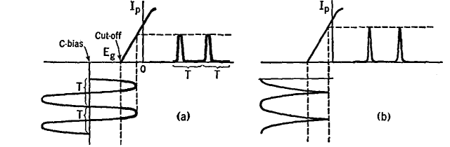
Instead of producing pulses by applying square waves to an RC circuit, as just described, a second method may be used where a sinusoidal e.m.f. is applied to the grid of a tube biased way beyond cutoff, so that only the tips of the applied wave cause plate current to flow. This is illustrated at (a) in Fig. 30 F.
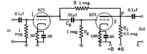
With this biasing method, pulses of from 100- to 500-microseconds duration can be produced, spaced at small or large time intervals T one from the other. A circuit for this purpose is shown in Fig. 30 G, where the tube at the left is biased well beyond cutoff.
It will be noted that the resistor R is connected at P instead of at +B, as in the usual amplifier circuit. Then, when a pulse of current flows through R and R2,the added voltage drop across R2 assists in sharpening the pulse. In another circuit, the pulses may be sharpened to only a few microseconds width by applying the output of a full-wave rectified sine wave (through a phase-inverting tube) to a highly biased amplifier tube, as indicated at (b) in Fig. 30 F.
|
||||||||
| Home Some Special Circuits Pulse Generators |
|
|||||||

Last Update: 2009-11-01