| Electronic Transformers and Circuits is a free introductory textbook on transformers and related circuits. See the editorial for more information.... |

|

Home  Electronic Control Transformers Electronic Control Transformers  Demodulators Demodulators |
||||||||||||


|
||||||||||||
Demodulators
Demodulators or detectors measure phase or amplitude variations which are used to convey intelligence or control another device. A circuit often used for phase detection is shown in Fig. 199.
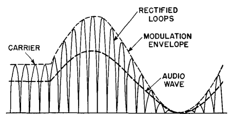
Modifications of this circuit made to eliminate the vector difference voltage or to reduce the degree of amplitude modulation are known as balanced and ratio detectors.(1) As used in servo control, the demodulator produces d-c output which changes polarity when one voltage reverses with respect to the other; in this case e2 adds directly to one voltage e1 and subtracts from the other. The lower vector diagram shows how a voltage e2 - e1 causes a low difference voltage on diode A and a large sum voltage on B to produce a net d-c output voltage. Transformers in phase-reversal demodulators are usually iron-cored. Both transformers T1 and T2 should have low exciting current so that the phase angle between the voltages to be measured is not appreciably increased. For the same reason, the source impedances should be small; when this is not possible, the transformers should be matched. Figure 131 shows how necessary this is. With equal source and load resistances, several degrees of phase shift are introduced even if the ratio of transformer reactance to source resistance is 10 : 1. Variations in this reactance cause errors in the phase-demodulator output. In a-m receivers, the received signal is modulated radio frequency. If 100 per cent amplitude modulation is used, the r-f amplitude is varied from 0 to 200 per cent at an audio-frequency rate. The detector, or demodulator, of the receiver first rectifies the r-f signal and then eliminates the r-f component, leaving only audio frequencies in the output. A rectified signal, before the r-f is eliminated, is shown in Fig. 200.
Demodulation is accomplished in the circuit of Fig. 201 by means of diode 6H6-2.
Each half of the r-f cycle is rectified and the d-c power is absorbed in resistor R3. Audio power is bypassed around R3 by capacitor C2, and the voltage is impressed upon the primary of transformer T2. If an amplitude-modulated wave is used in this amplifier, the output voltage of winding S1 on transformer T1 has the form shown in Fig. 200. The first few cycles are shown as full-wave rectified loops with constant amplitude, that is, with no modulation. The audio output for this section of the wave is zero. A sine-wave envelope of 100 per cent modulation is shown in the rest of the figure. Average voltage left after the carrier frequency half-loops have been absorbed by the r-f filter L1C1 is the audio voltage impressed on transformer T2. The method of demodulation just described is known as diode demodulation. It is often accomplished by means of a single diode, and then every other lobe of the wave in Fig. 200 is omitted. Methods are in use also for demodulation with a triode, in which some amplification of the demodulated wave is obtained.
|
||||||||||||
Home  Electronic Control Transformers Electronic Control Transformers  Demodulators Demodulators |
||||||||||||
Last Update: 2011-02-17


