| Electronic Transformers and Circuits is a free introductory textbook on transformers and related circuits. See the editorial for more information.... |

|

Home  Magnetic Amplifiers Magnetic Amplifiers  Feedback in Magnetic Amplifiers Feedback in Magnetic Amplifiers |
||||||||


|
||||||||
Feedback in Magnetic Amplifiers
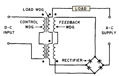
If a rectifier is interposed between the reactor and load, and a separate winding on the reactor is connected to this rectifier as in Fig. 210, it is possible to obtain sufficient power from the rectifier to supply most of the control power. If the control power from the rectifier furnishes the ampere-turns represented by the straight line in Fig. 209, the amplifier is said to have 100 per cent "feedback."
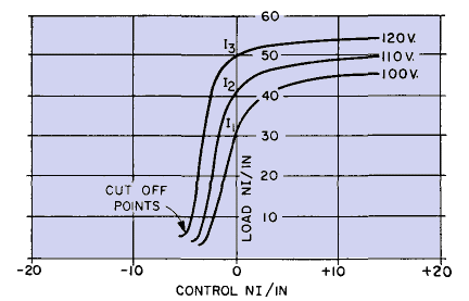
Typical transfer curves for a simple magnetic amplifier are plotted in Fig. 209 for three a-c supply voltages: 100, 110, and 120 volts. A 100 per cent feedback line intersects the transfer, curves at I1, I2, and I3, respectively. The control NI/in. are furnished by the feedback, except for the control current difference between the feedback line and the transfer curve. Positive control current is required when the transfer curve is at the right, and negative current when it is at the left, of the feedback line. Net control NI/in. for the three voltages are plotted in Fig. 211 with expanded abscissa scale.
Now the transfer curve is asymmetrical. Most of the amplifier gain occurs with negative control current changes. On the steep parts of the transfer curves, gain is fairly linear and greatly exceeds the gain of simple amplifiers. Below the steep parts, output current reaches a minimum but remains small with relatively large excursions of negative control current. These current minima are called cut-off points. Reference to Fig. 207 shows that cut-off current is IN, the normal exciting current at supply voltage E. With positive control, current output levels off to a nearly constant value, depending on the voltage. Feedback causes output current to be quite dependent on variations in a-c supply voltage, because IN has a greater effect than in simple amplifiers. Computing control current for transfer curves with feedback as described in the preceding paragraph involves a small difference between two large quantities. Minor measurement errors in the original data cause large inaccuracies in the feedback transfer curves of Fig. 211. A more accurate derivation of 100 per cent feedback transfer curves is given in Hysteresis Loops and Transfer Curves.
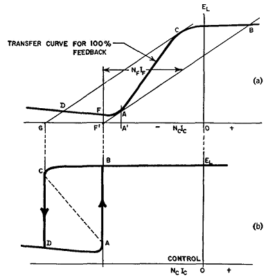
To the left of the cut-off points, the transfer curve rises slowly toward the left along a straight line, as in Fig. 212(a). This line corresponds to 100 per cent negative feedback; it is practically linear, but gain is much reduced. The transfer curves of Fig. 211 would, if continued to the left, merge into such a line. Polarities in Fig. 210 are for positive feedback with positive direct current entering the control winding at the top. Negative feedback is obtained if the control current is reversed. If series feedback is derived as shown in Fig. 210, the feedback current is EL/RL. It is possible to connect the feedback circuit across the load to obtain voltage feedback. To conserve power, the feedback resistance should be large relative to RL.
|
||||||||
Home  Magnetic Amplifiers Magnetic Amplifiers  Feedback in Magnetic Amplifiers Feedback in Magnetic Amplifiers |
||||||||
Last Update: 2011-02-17


