| Electronic Transformers and Circuits is a free introductory textbook on transformers and related circuits. See the editorial for more information.... |

|

Home  Magnetic Amplifiers Magnetic Amplifiers  Self-Saturated Magnetic Amplifier Circuits Self-Saturated Magnetic Amplifier Circuits |
||||||||||||||||||||||||||||||||||||||||||||||||||||||||||||||||


|
||||||||||||||||||||||||||||||||||||||||||||||||||||||||||||||||
Self-Saturated Magnetic Amplifier Circuits
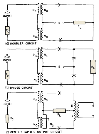
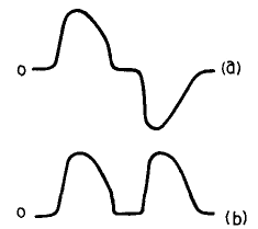
In Fig. 217 three single-phase circuits are diagrammed which comprise two of the half-wave elements described in the preceding sections. These circuits are discussed briefly below. (a) Doublet Circuit. This is really two half-wave circuits working into a common load. Rectifier polarities are such as to cause a-c voltage to appear across the load, as in Fig. 218(a).
The wave shape departs somewhat from alternately reversed half-waves. In the doubler, the reactor which is carrying load current during a given half-cycle causes a reduction in the resetting voltage, and therefore in the time rate of resetting flux change of the other reactor. This increases the output and gain for a given control current compared to the half-wave circuit but has no effect on current minima at the cutoff points (see Fig. 211).
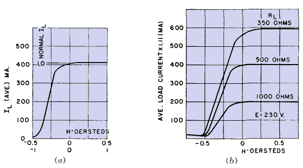
(b) Single-Phase Bridge Circuit. Here two extra rectifiers isolate the two reactors at all times, and the wave form is like that of the half-wave rectifier, except that it occurs twice each cycle. Load current is d-c; that is, both reactors produce load current of the same polarity, as in Fig. 218(b). Because of the isolation of the two reactors, the transfer curve closely follows a dot-dash line like that in Fig. 216 if the core is grain-oriented nickel steel, or a similar line between a-c and d-c loops for other core material. Control resistance Rc affects output in a manner similar to that mentioned for the doubler. (c) Center-Tap D-C Circuit. Although the reactors are not isolated in this circuit, load and resetting currents are still the same as for the bridge circuit, and hence the transfer curve has the same shape, unless the rectifier reverse currents are appreciable. Then gain is appreciably reduced. In all these single-phase circuits, the load current is twice that of the half-wave circuit. Therefore transfer curves may be predicted from B-H loops as in Hysteresis Loops and Transfer Curves, but ordinates are multiplied by E/2.22RLBS, and the vertical displacement is E/2.22RL. From these multipliers it can be seen that output current is proportional to supply voltage E, and therefore power gain is proportional to E2. In this respect, a self-saturated amplifier contrasts with a simple magnetic amplifier, the output current of which is nearly independent of E, for rectangular B-H loop core material. At least this is true below maximum current, or current flow over a complete half-cycle. As an example of the manner in which a transfer curve is found from the B-H loop, suppose that, in a given self-saturated amplifier, Fig. 216 is the B-H loop, supply voltage E = 230 v, RL = 500 ohms, Bs = 14.7 kilogauss. The ordinate multiplier is 230/(2.22 · 500 · 14.7) = 0.0141, and displacement is 230/(2.22 · 500) = 0.207. Table XV indicates the change in ordinates.
TABLE XV. DERIVATION OF TRANSFER CURVE FROM B-H LOOP (Fig. 216)
The last two columns of the table are plotted in Fig. 219 (a) as load current in milliamperes.
Also indicated is the "normalized" value of unity for maximum output current. For any load impedance the same calculated transfer curve can be used, and all ordinates multiplied by E/1.11RL. Abscissas may be normalized likewise, with cut-off H = -1.0. Normalized output current at cut-off is ΔN = INRL/E. Cut-off control current is most accurately found from H corresponding to -Br. This is H = -0.5 in Fig. 216. These relations are, of course, idealized, but they are still very useful in practical work. For example, winding resistance RG and rectifier forward resistance RF reduce load current and output power, but these resistances may be added to the actual RL arithmetically to obtain total resistance RT = RG + RF + RL. Then the transfer curve ordinates are
displaced vertically by
Output current and power are reduced somewhat by these inevitable resistances. This can be verified in Fig. 219(b) which is a plot of transfer curves for an actual doubler amplifier with E = 230 v, with 350-, 500-, and 1,000-ohm load resistances, and with average load current · 1.11 as read directly on the output meter. The 500-ohm load resistance curve is approximately the same as Fig. 219 (a); this means that RF + RG ≈ 0.11RL in this particular amplifier. The accuracy of Fig. 219 (a) is evidently poorest at cut-off. Upward slope at control currents more negative than cut-off is not shown at all. For the most practical region, i.e., to the right of cut-off, the calculated curve is eminently useful. Additional windings are often used on the reactors for control purposes. One common winding, called a bias winding, carries negative control current. The function of this winding is to maintain low output in the absence of control current. Thus in Fig. 211, with E = 120, - 5NI//in. of bias magnetizing force keeps the amplifier load NI/in. at 5. Then positive control current raises the load current to the desired value. Most of the gain is obtained with less than + 5NI/in. control magnetizing force. Additional control windings are used for adding or subtracting input signals. This provides a simple means of combining several control functions in one magnetic amplifier. Response time in a self-saturated amplifier is longer than in a simple amplifier, but the gain per second is much greater. The time constant is
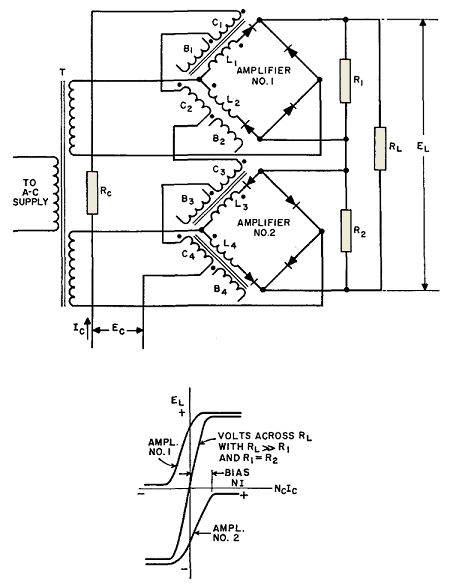
where Td = time for 63 per cent response to step input Equation 123 is valid for Td down to approximately 4 cycles minimum. Although smaller Td may be obtained, it does not follow equation 123. Push-pull amplifiers are used to provide a-c or d-c output, with the output polarity dependent on input polarity. A d-c push-pull circuit which senses input polarity is shown in Fig. 220.
Bias windings on each reactor carry current in such directions that amplifier outputs cancel for Ec = 0. For positive Ec, amplifier 1 produces positive EL, and for negative Ec, amplifier 2 produces negative EL. This circuit has low efficiency, owing to the power dissipated in the balance resistances R1 and R2 but has linear output. It is important, wherever two or more reactors are used together in magnetic amplifiers, that the reactors be alike in turns and in cores. Cores are generally selected to "match," with closely duplicated B-H characteristics. It is not feasible to compensate core differences in balanced amplifiers by bias adjustments and still obtain linear output.
|
||||||||||||||||||||||||||||||||||||||||||||||||||||||||||||||||
Home  Magnetic Amplifiers Magnetic Amplifiers  Self-Saturated Magnetic Amplifier Circuits Self-Saturated Magnetic Amplifier Circuits |
||||||||||||||||||||||||||||||||||||||||||||||||||||||||||||||||
Last Update: 2011-01-24


