| Electronic Transformers and Circuits is a free introductory textbook on transformers and related circuits. See the editorial for more information.... |

|

Home  Pulse and Video Transformers Pulse and Video Transformers  Total Response Total Response |
|||||||||||||||||||


|
|||||||||||||||||||
Total Response
By means of the curves we can now construct the pulse shape delivered to load R2. Suppose that a transformer with the following properties is required to deliver a flat top pulse of 15 microseconds' duration.
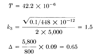
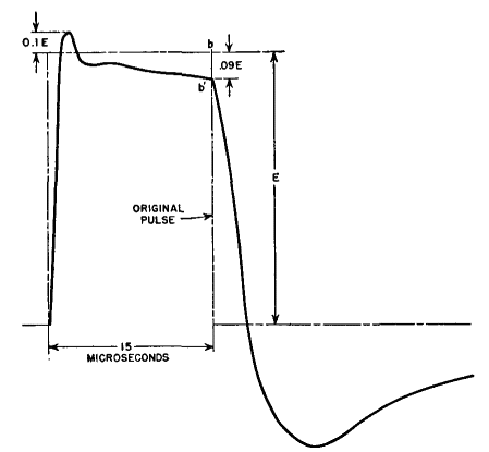
From the expressions given in Fig. 230 m = 2.34 · 106 T = 1.8 microseconds k1 = 0.68 The front of the wave follows a curve between those marked k1 = 0.4 and k1 = 0.8 in Fig. 230. Value Ea is reached in 0.5T or 0.85 microsecond, and an overshoot of about 10 per cent occurs in 1.2 microseconds. The top of the wave slopes down to a voltage determined by the product τR1/Le = 0.12, and by a curve between those for R2 = ∞ and R2 = 2R1 in Fig. 234. Voltage E' at b is evidently 0.9Ea. The trailing edge is found from Fig. 235. Here
Load voltage reaches zero in 0.05T or 2.11 microseconds. The negative loop has maximum amplitude of 33 per cent E' at 0.2T or 8.44 microseconds beyond the pulse edge b. The pulse delivered to load R2 is shown in Fig. 236, in terms of E instead of Ea.
So far we have assumed that the pulse source is disconnected at the end of the pulse. In some applications the source remains connected.
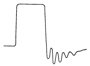
Superposed backswing oscillations are discussed more fully in Design of Pulse Transformers. Because of the distributed nature of leakage inductance and capacitance, higher-frequency superposed oscillations may sometimes occur even when the load is disconnected at the end of a pulse. By their very nature, the conditions for these oscillations are difficult to state with certainty, but if oscillations occur on the front edge they are likely to appear on the trailing edge, superposed on the voltage back-swing.
|
|||||||||||||||||||
Home  Pulse and Video Transformers Pulse and Video Transformers  Total Response Total Response |
|||||||||||||||||||
Last Update: 2011-01-24


