| The ebook FEEE - Fundamentals of Electrical Engineering and Electronics is based on material originally written by T.R. Kuphaldt and various co-authors. For more information please read the copyright pages. |

|
Home  Semiconductors Diodes and Rectifiers Inductor commutating circuits Semiconductors Diodes and Rectifiers Inductor commutating circuits |
|


|
  |
|
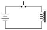
Inductor commutating circuitsKickback, inductiveA popular use of diodes is for the mitigation of inductive "kickback:" the pulses of high voltage produced when direct current through an inductor is interrupted. Take for example this simple circuit:
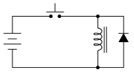
When the pushbutton switch is actuated, current goes through the inductor, producing a magnetic field around it. When the switch is de-actuated, its contacts open, interrupting current through the inductor, and causing the magnetic field to rapidly collapse. Because the voltage induced in a coil of wire is directly proportional to the rate of change over time of magnetic flux (Faraday's Law: e = NdΦ/dt), this rapid collapse of magnetism around the coil produces a high voltage "spike." Commutating diodeIf the inductor in question is an electromagnet coil, such as might be seen in a solenoid or relay (constructed for the purpose of creating a physical force via its magnetic field when energized), the effect of inductive "kickback" serves no useful purpose at all. In fact, it is quite detrimental to the switch, as it will cause excessive arcing at the contacts, greatly reducing their service life. There are several practical methods of mitigating the high voltage transient created when the switch is opened, but none so simple as the so-called commutating diode:
In this circuit, the diode is placed in parallel with the coil, in such a way that it will be reverse-biased when DC voltage is applied to the coil through the switch. Thus, when the coil is energized, the diode conducts no current:
However, when the switch is opened, the coil's inductance responds to the decrease in current by inducing a voltage of reverse polarity, in an effort to maintain current at the same magnitude and in the same direction. This sudden reversal of voltage polarity across the coil forward-biases the diode, and the diode provides a current path for the inductor's current, so that its stored energy is dissipated slowly rather than suddenly:
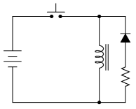
As a result, the voltage induced in the coil by its collapsing magnetic field is quite low: merely the forward voltage drop of the diode, rather than hundreds of volts as before. Thus, the switch contacts experience a voltage drop equal to the battery voltage plus about 0.7 volts (if the diode is silicon) during this discharge time. Commutating diode Commutation SnubberIn electronics parlance, commutation refers to the reversal of voltage polarity or current direction. Thus, the purpose of a commutating diode is to act whenever voltage reverses polarity, in this case, the voltage induced by the inductor coil when current through it is interrupted by the switch. A less formal term for a commutating diode is snubber, because it "snubs" or "squelches" the inductive kickback. Faraday's LawA noteworthy disadvantage of this method is the extra time it imparts to the coil's discharge. Because the induced voltage is clamped to a very low value, its rate of magnetic flux change over time is comparatively slow. Remember that Faraday's Law describes the magnetic flux rate-of-change (dΦ/dt) as being proportional to the induced, instantaneous voltage (e or v). If the instantaneous voltage is limited to some low figure, then the rate of change of magnetic flux over time will likewise be limited to a low (slow) figure. If an electromagnet coil is "snubbed" with a commutating diode, the magnetic field will dissipate at a relatively slow rate compared to the original scenario (no diode) where the field disappeared almost instantly upon switch release. The amount of time in question will most likely be less than one second, but it will be measurably slower than without a commutating diode in place. This may be an intolerable consequence if the coil is used to actuate an electromechanical relay, because the relay will possess a natural "time delay" upon coil de-energization, and an unwanted delay of even a fraction of a second may wreak havoc in some circuits. Unfortunately, there is no way to eliminate the high-voltage transient of inductive kickback and maintain fast de-magnetization of the coil: Faraday's Law will not be violated. However, if slow de-magnetization is unacceptable, a compromise may be struck between transient voltage and time by allowing the coil's voltage to rise to some higher level (but not so high as without a commutating diode in place). The following schematic shows how this may be done:
A resistor placed in series with the commutating diode allows the coil's induced voltage to rise to a level greater than the diode's forward voltage drop, thus hastening the process of de-magnetization. This, of course, will place the switch contacts under greater stress, and so the resistor must be sized to limit that transient voltage at an acceptable maximum level.
|
|
| Home Semiconductors Diodes and Rectifiers Inductor commutating circuits |
|


Last Update: 2010-12-01