| Practical Physics is a free textbook on basic laboratory physics. See the editorial for more information.... |
|
Home  Mirrors and Lenses The Testing of Plane Surfaces Mirrors and Lenses The Testing of Plane Surfaces |
||||||


|
  |
|||||
The Testing of Plane Surfaces
The planeness of a reflecting surface can be tested more accurately by optical means than in any other way. The method depends on the fact that a pencil of parallel rays remains parallel after reflexion at a plane surface.
We can thus easily test the planeness of a surface. If the surface is found to be defective, the defect may arise in two ways: (a) From the surface being part of a regular reflecting surface - a sphere or paraboloid, for example - and not plane. In this case a distinct image of the distant object is formed by reflexion at the surface; but, the surface not being plane, the pencils forming the image will not be parallel, and therefore, in order to see it, we must alter the focussing of the telescope. We shall show shortly how, by measuring the alteration in the position of the eye-piece of the telescope, we can calculate the radius of curvature of the surface. (b) In consequence of the general irregularity of the surface. In this case we cannot find a position of the eyepiece, for which we get a distinct image formed - the best image we can get will be ill-defined and blurred. We may sometimes obtain a definite image by using only a small part of the reflecting surface, covering up the rest. This may happen to give regular reflexion, and so form a good image. To test roughly the planeness of a surface or to measure its curvature, if the latter be considerable, an ordinary observing telescope may be used. Focus it through the open window on some distant, well-defined object A vane, if one be visible, will be found convenient. Place the surface to reflect some of the rays from the distant object at an angle of incidence of about 45°, and turn the telescope to view the reflected image. If the image is in focus, the surface is plane. If by altering the focus we can again get a well-defined image, the surface reflects regularly, and is a sphere or something not differing much from a sphere; if the image can never be made distinct and clear, the surface is irregular. I^t us suppose we find that by a slight alteration in the focus we can get a good image, we shall show how to measure the radius of curvature of the surface. To do this accurately, we require a rather large telescope with an object-glass of considerable focal length, say about 1 metre. It will be better, also, to have a collimator. This consists of a tube with a narrow slit at one end of it and a convex lens at the other, the focal length of the lens being the length of the tube; the slit is accordingly in the principal focus of the lens, and rays of light coming from it are rendered parallel by refraction at the lens. Sometimes a tube carrying the slit slides in one carrying the lens, so that the distance between the two can be adjusted. We shall suppose further that there is a distinct mark on the telescope tube and another on the sliding tube to which the eye-piece is attached. We shall require to measure the distance between these marks; the line joining them should be parallel to the axis of the telescope. The telescope should alsb be furnished with cross-wires. Focus the eye-piece on the cross-wires. Turn the telescope to the distant object and adjust the focussing screw, thus moving both eye-piece and cross-wires relatively to the object-glass, until the object is seen distinctly and without any parallax relatively to the cross-wires. To determine when this is the case move the eye about in front of the eye-piece and note that there is no relative displacement of the image and the cross-wires. Measure with a millimetre scale, or otherwise, the distance a, say, between the two marks on the telescope tubes. Repeat the observation four or five times. Take the mean of the distances observed and set the instrument so that the distance between the marks is this mean. Now point the telescope to the collimator, place a lamp behind the slit of the latter, and adjust the distance between the slit and the lens until the slit appears to be properly focussed when viewed through the telescope. When this is the case the rays issuing from the collimator lens are accurately parallel. Place the reflecting surface to reflect at an angle of incidence of about 45° the light from the collimator, and turn the telescope to view it. When the reflecting material is transparent and has a second surface nearly parallel to the first, the light reflected from it will form an image which will be visible and may cause inconvenience; if this be so, cover the second surface with a piece of wet coloured blotting-paper. We require to know the angle of incidence. To find this accurately it would be necessary to use for the collimator the collimator of a spectrometer and to mount the surface on the table of the spectrometer. The angle then could be found as described in §62. For most purposes, however, the angle of incidence can be found by some simpler means, e.g. by setting the telescope and collimator so that their axes are at right angles, determining when this is the case by eye or with the help of a square, and then placing the surface so as to bring the reflected image of the slit into the field of view; the angle required will then not differ much from 45°. Let us call it φ. The image seen will not be in focus, but it can be rendered distinct by altering the position of the eye-piece of the telescope. Let this be done four or five times, and measure each time the distance between the two marks on the telescope tubes; let the mean value be b.
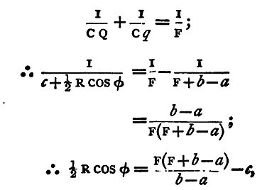
Observe also the distance c between the object-glass and the reflecting surface, this distance being measured parallel to the axis of the telescope. Let F be the focal length of the object-glass, φ the angle of incidence, then R the radius of curvature of the reflecting face is, if that face be convex, given by the formula
For let A B (fig. 32) be a ray incident obliquely at B at an angle φ, A' B' an adjacent parallel ray; after reflection they will diverge from a point Q behind the surface, and falling on the object-glass C be brought to a focus at q, there forming a real image of the distant object, which is viewed by the eye-piece D. Let F be the principal focus of the object-glass. Then when the distant object was viewed directly, the image formed by the object-glass was at F, and if D' be the position of the eye-piece adjusted to view it, we have D'F = Dq, and hence Fq = DD', but DD' is the distance the eye-piece has been moved; hence we have
Also CB = c, and since Q is the primary focal line(1) of a pencil of parallel rays incident at an angle φ
But
and
In the case of a concave surface of sufficiently large radius it will be found that b is less than a; the eye-piece will require pushing in instead of pulling out; and the radius of curvature is given by the formula
We have supposed hitherto that the slit is at right angles to the plane of reflexion, and the primary focus, therefore, the one observed. If the slit be in the plane of reflexion the image seen will be formed at the secondary focal line, and the formula will be
a, b, c, &c., having the same meaning as before. Again let us suppose that the plate of material examined has two faces, each of which has been found to be plane. We can use the method to determine if they are parallel, and if not to find the angle between them. For make the adjustments as before, removing, however, the wet blotting paper from the back face. If the two faces be strictly parallel only one image of the slit will be seen, for the rays from the front and back surfaces will be parallel after reflexion. If the faces be not parallel, two images of the slit will be seen. Let us suppose that the angular distance between the two images can be measured either by the circle reading of the spectrometer, if the spectrometer telescope is being used, or by the aid of a micrometer eye-piece if that be more convenient; let this angular distance be D; then the angle between the faces is given by the equation
where φ' is the angle of refraction, corresponding to an angle of incidence φ, and μ the refractive index of the material; D and i are supposed so small that we may neglect their squares. For (fig. 33) let ABC, ADE be the two faces of the prism, PBQ, PBDCQ' the paths of two rays; let QB, Q'C meet in O, then QOQ' = DBAD = i.
Hence
Again
Also since DC and CQ' are the directions of the same ray inside and outside respectively,
neglecting D2 and i2. But
Again, it may happen that one or both faces of the piece of glass are curved; it will then act as a lens, and the following method will give its focal length. The method may be advantageously used for finding the focal length of any long-focussed lens. Direct the telescope to view the collimator slit, and focus it; interpose the lens in front of the object-glass. The focus of the telescope will require altering to bring the slit distinctly into view again. Let us suppose that it requires to be pushed in a distance x. Let c be the distance between the lens and the object-glass of the telescope, then the parallel rays from the collimator would be brought to a focus at a distance f behind the lens, i.e. at a distance f-c behind the object-glass; they fall, however, on the object-glass, and are brought by it to a focus at a point distant F-x from the glass.
and from this we find
If the lens be concave, the eye-piece of the telescope will require pulling out a distance x suppose; and in this case the rays falling on the object-glass will be diverging from a point at a distance f+c in front of it, and will converge to a point at a distance F+x behind it
We infer, then, that if the eye-piece requires pushing in the lens is convex, and if it requires pulling out it is concave. Moreover, we note that all the above formulae both for reflexion and refraction are simplified if F=c; that is to say, if the distance between the object-glass and the reflecting surface or lens, as the case may be, is equal to the focal length of the object-glass. If this adjustment be made, and if x be the displacement of the eye-piece in either case, we have for the radius of curvature of the surface
and for the focal length
Experiments.
(1) Measure the curvature of the faces of the given piece of glass. Enter results thus: -
|
||||||
| Home Mirrors and Lenses The Testing of Plane Surfaces |
|
|||||


Last Update: 2011-03-27