| Practical Physics is a free textbook on basic laboratory physics. See the editorial for more information.... |

|
Home  Electricity Absolute Measure of the Current in a Wire Electricity Absolute Measure of the Current in a Wire |
||


|
  |
|
Absolute Measure of the Current in a Wire
The wire in question is bent into the form of a circle, which is placed approximately in the plane of the magnetic meridian. This is done by using a long magnet mounted as a compass-needle and placing the plane of the wire by eye parallel to the length of this magnet The two ends of the wire are brought as nearly into contact as is possible, and then turned parallel to each other at right angles to the plane of the circle; they are kept separate by means of a small piece of ebonite, or other insulating material. The mirror is usually slightly concave, and by adjusting the distance between the scale and the mirror, a distinct image of the slit can be formed on the scale, and its position accurately determined In some cases it is convenient to stretch a thin wire vertically across the middle of the slit, and read the position of its image. If an image cannot be obtained by simply varying the distance, through the mirror not being concave, or from some other defect, a convex lens of suitable focal length may be inserted between the slit and the mirror; by adjusting the lens the image required can be obtained. When there is no current passing through the wire the image should coincide with the division of the scale which is vertically above the slit To determine whether or not the scale is parallel to the mirror, mark two points on the scale near the two ends, and equidistant from the middle point, and measure with a piece of string the distances between each of these two points and a point on the glass face of the mirror-case exactly opposite the centre of the mirror. If these two distances be the same, the scale is rightly adjusted; if they be not, turn the scale, still keeping the image of the slit vertically above the slit, until they become equal. Then it is clear that the scale is at right angles to the line which joins its middle point to the mirror, and that this line is also at right angles to the mirror. The scale, therefore, is parallel to the mirror. If now the ends of the wire be connected with the poles of a Daniell's battery, or with some other apparatus which maintains a difference of potential between them, a current will flow in the wire. The magnet and mirror will be deflected, and the spot of light will move along the scale, coming to rest after a short time in a different position. Note this position, and suppose the distance between it and the original resting-point to be xl scale divisions - it will be convenient when possible to use a scale divided into centimetres and millimetres. - Reverse the direction of the current in the circuit, either by using a commutator or by actually disconnecting it from the battery, and connecting up in the opposite way. The spot will be deflected in the opposite direction through, let us suppose, x2 scale divisions. If the adjustments were perfect, we ought to find that x1 and x2 were equal; they will probably differ slightly. Let their mean be x. Then it can be shown that, if the difference between x1 and x2 be not large, say about 5 scale divisions, when the whole deflexion is from 100 to 200 divisions, we may take x as the true value of the deflexion which would have been produced if the scale and mirror had been perfectly adjusted. Let us suppose further that a large number of scale divisions - say 500 - occupies l cm. Then the number of centimetres in x scale divisions is xl/500. Measure the distance between the centre of the mirror and the scale, and let it be a cm. Measure also the diameter of the circle in centimetres, estimating it by taking the mean of measurements made in five different directions across the centre. Allow for the thickness of the wire, and so obtain the mean diameter of the core of the circle formed by the wire y let it be 2 r centimetres.
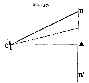
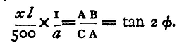
Let BAB' (fig. 57) be the scale, A the slit, and B the point at which the image is formed; let C be the centre of the mirror; the ray of light has been turned through the angle ACB, and if φ be the angle through which the magnet and mirror have moved, then ACB = 2 φ, for the reflected ray moves through twice the angle which the mirror does (see §48). Moreover, the distances CA and AB have been observed, and we have AB = xl/500, CA = 0. Thus
From this equation then 2φ can be found, using a table of tangents, and hence tanφ, by a second application of the table. But the circle was placed in the magnetic meridian, parallel, therefore, to the magnet, and the force due to the current is consequently at right angles to that due to the earth. We have, therefore, from the last section, if i represent the current,
We have shown in §69 how H is to be found, and the values of r and tanφ have just been determined; the value of π is, of course, 3.14159, and H may be taken as 0.180. Thus we can measure i in C.G.S. absolute units. To find i in amperes we have to multiply the result by 10, since the C.G.S. unit of current contains 10 amperes. The repetition of this experiment with circles of different radii would serve to demonstrate the accuracy of the fundamental law of the action of an electric current on a magnet. The experiment may, by a slight modification, be arranged with the more direct object of verifying the law in the following manner. Set up two coils concentrically, in the magnetic meridian, with a needle at their common centre. Let the one coil consist of a single turn of wire and the other of two turns, and let the radius of the second be double that of the first. Then on sending the same current through either coil the deflexion of the needle will be found to be the same; the best way, however, of demonstrating the equality is to connect the two coils together so that the same current passes through both, but in opposite directions; the effect on the needle for the two coils respectively being equal and opposite, the needle will remain undeflected. We are indebted to Professor Poynting, of Birmingham, for the suggestion of this method of verifying the fundamental electro-magnetic law. It should be noticed that the formula for the deflexion does not contain any factor which depends on the magnetism of the suspended needle; in other words, the deflexion of a galvanometer is independent of the magnetic moment of its needle. This fact may also be experimentally verified by repeating the experiment with different needles and noticing that the deflexion is always the same for the same current. Experiment. - Determine the strength of the current from the given battery when running through the given circle. Enter results thus: Observations for diameter, corrected for thickness of the wire: 32 cm 32.1 cm 31.9 cm 32 cm 32.1 cm Mean-value of r: 16.01 cm x = 165 divisions of scale. l = space occupied by 500 divisions = 31.7 cm a = 60.7 cm tan 2φ = 0.1723 tan φ = -0.0816. i = 0.0342 C.G.S. unit = 0.342 ampere.
|
||
| Home Electricity Absolute Measure of the Current in a Wire |
|
|

Last Update: 2011-03-27