| Practical Physics is a free textbook on basic laboratory physics. See the editorial for more information.... |

|
Home  Electricity Ohm's Law Resistance Boxes Electricity Ohm's Law Resistance Boxes |
|||||


|
  |
||||
Resistance Boxes
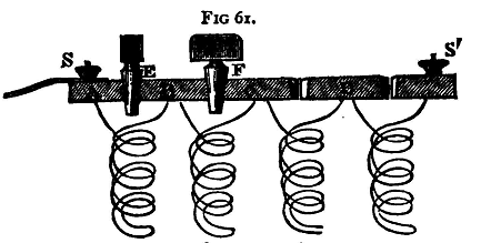
For practical use resistance coils are generally grouped together in boxes. The top of the box is made of nonconducting material, and to it are attached a number of stout brass pieces shown in fig. 61 at A, B, C, D. A small space is left between the consecutive brass pieces, and the ends of these pieces are ground in such a way that a taper plug of .brass can be inserted between them and thus put the two consecutive pieces into electrical connection. The coils themselves are made of German-silver or platinum-silver wire. The wire is covered with silk or some other insulating material. A piece of wire of the required resistance is cut off and bent double. It is then wound on to a bobbin of ebonite or other insulating material. The bobbins are not drawn in the figure. The two ends are soldered to two consecutive brass pieces in the box, the bobbin being fixed to the under side of the lid of the box. The coils when complete are covered with paraffin to maintain a good insulation.
Let A, B be the two brass pieces, and suppose a current flowing from A to B; if the plug is in its place, the current can pass through it, and the resistance between A and B is infinitesimally small, provided always that the plug fits properly. If, however, the plug be removed, the current has to flow through the coil itself; so that by removing the plug the resistance of the coil may be inserted in the circuit between A and B. The coils in a box are generally arranged thus:
Thus, if there be the twelve coils as above, by taking out suitable plugs we can insert any desired integral number of units of resistance between 1 and 1000, like weights in the balance. Binding screws, S, S', are attached to the two extreme brass pieces, and by means of these the box can be connected with the rest of the circuit. The coils are wound double, as described, to avoid the effects which would otherwise arise from self-induction,(1) and also to avoid direct magnetic action on the needle of the galvanometer.
|
|||||
| Home Electricity Ohm's Law Resistance Boxes |
|
||||

Last Update: 2011-03-15