| Practical Physics is a free textbook on basic laboratory physics. See the editorial for more information.... |

|
Home  Electricity Comparison of the Capacities of two Condensers Electricity Comparison of the Capacities of two Condensers |
||


|
  |
|
Comparison of the Capacities of two Condensers
(1) Approximate Method of Comparison. Charge the two condensers alternately with the same battery through the same galvanometer, and observe the throws. Let C1, C2 be the two capacities, β1, β2 the corresponding throws, the mean of several being taken in each case. Then since the differences of potential to which the condensers are charged are the same for the two, we have (pp. 469, 471).
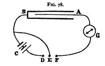
For making contact a Morse Key is convenient. In this apparatus there are three binding screws D, E, F (fig. 78) attached to a plate of ebonite, or other good insulating material, above which is a brass lever. F is in connection with the fulcrum of the lever, E with a metal stud under one end, and D with a similar stud under the other. A spring keeps the front end of the lever in contact with the stud connected to E, so that E and F are, for this position of the lever, in electrical communication.
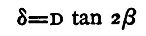
On depressing the other end of the lever this contact is broken, and the end depressed is brought into contact with the stud connected with D. Thus E is insulated, and D and F put into communication. In fig. 78, A and B are the two poles of the condenser, G is the galvanometer, and c the battery. One pole of the battery is connected with B, the other pole with D; A is connected with the galvanometer G, and F with the other pole of the galvanometer, while B is also in connection with E. In the normal position of the key one pole of the battery, connected with D, is insulated and the two poles of the condenser B and A are in connection through E and F. Let the spot of light come to rest on the galvanometer scale, and observe its position. Depress the key, thus making contact between D and F, and observe the throw produced. The spot will swing back through the zero to nearly the same distance on the other side. As it returns towards the zero, and just before it passes it for the second time, moving in the direction of the first throw, release the key. This insulates D and discharges the condenser through the galvanometer, the electricity tends to produce a throw in the direction opposite to that in which the spot is moving, which checks the needle, reducing it nearly to rest. Wait a little until it comes to rest, and then repeat the observation. Let the mean of the throws thus found be δ1. Replace the first condenser by the second and make a second similar observation; let the mean of the throws measured as before along the scale be δ2. To eliminate the effect of alteration in the E.M.F. of the battery repeat the observations for the first condenser, and let the mean of the throws be δ1'. Now δ1 and δ1' should, if the battery has been fairly constant, differ extremely little; the mean (δ1+δ1')/2 should be taken for the throw. Let D be the distance between the scale and the galvanometer mirror. Then, as we have seen (§71)
and
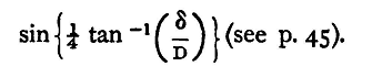
so that
And if the ratio δ/D be small we may put δ/4D for
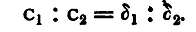
Hence we find from (1) and (2)
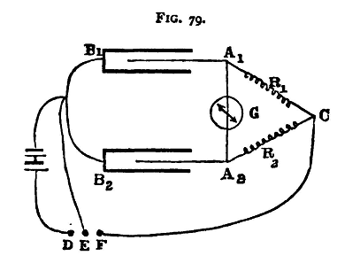
This may be obviated by a judicious use of a magnet held in the hand of the observer, and reversed in time with the galvanometer needle, or still better by having near the galvanometer a coil of wire in connection with a second battery and a key. On making contact with the key at suitable times the current in the coil produces electro-magnetic effects, by means of which the needle may gradually be stopped. (2) Null Method of Comparing Capacities. The method just given has the defects common to most methods which turn mainly on measuring a galvanometer deflexion. The method which we now proceed to describe resembles closely the Wheatstone bridge method of measuring resistance. Two condensers are substituted for two adjacent arms of the bridge; the galvanometer is put in the circuit which connects the condensers. Fig. 79 shows the arrangement of the apparatus. A1B1, A2B2, are the two condensers; B1B2 are in connection with each other and with one pole of the battery; A1, A2 are connected through resistances R1, R2 respectively, to the point C, which is also in connection with F, one of the electrodes of the Morse key. The second pole of the battery is connected with D on the Morse key, while E, the middle electrode of the key, is connected to B1 and B2. In the normal position of the key the plates of the condenser are connected through E and F. On depressing the key the contact between E and F is broken, and contact is made between D and F; and the condensers are thus charged.
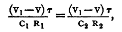
In general it will be found that on thus making contact the galvanometer needle is suddenly deflected. We shall show, however, that if the condition C1R1 = C2R2 hold, C1, C2 being the two capacities, there will not be any current through the galvanometer, the needle will be undisturbed (see below). To compare the two capacities, then, the resistances R1 R2 must be adjusted until there is no effect produced in the galvanometer, by making or breaking contact, and when this is the case we have C1/C2 = R2/R1, and R1, R2 being known, we obtain the ratio C1/C2. In performing the experiment it is best to choose some large integral value, say 2000 ohms for R1, and adjust R2 only. We proceed to establish the formula C1R1 = C2R2 No current will flow from A1 to A2 if the potential of these two points be always the same. Let V0 be the constant potential of the pole of the battery in contact with B1 and B2, V1 that of the other pole. Let V be the common potential of A1 and A2 at any moment during the charging, and consider the electricity which flows into the two condensers during a very short interval τ. The potential at C is V1 and at A1 and A2 it is V at the beginning of the interval. The current along C A1 will be then (V1-V)/R1, and along C A2, (V1-V)/R2; and if the time τ be sufficiently small, the quantity which flows into the two condensers will be respectively (V1-V)τ/R1 and (V1-V)τ/R2. The inflow of this electricity will produce an increase in the potential of the plates A1 and A2; and since, if one plate of a condenser be at a constant potential, the change in the potential of the other plate is equal to the increase of the charge divided by the capacity, we have for the increase of the potential at A1 and A2 during the interval τ, when τ is very small, the expressions (V1-V)τ/C1R1 and (V1-V)τ/C2R2 respectively. By the hypothesis A1 and A2 are at the same potential at the beginning of the interval τ, if the two expressions just found for the increment of the two potentials be equal, then the plates will be at the same potential throughout the interval The condition required is
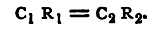
and this clearly reduces to
Thus, if C1R1 = C2R2 the plates A1, A2 will always be at the same potential, and in consequence no effect will be produced on the galvanometer. The complete discussion of the problem ('Philosophical Magazine', May 1881) shows that the total quantity of electricity which flows through the galvanometer during the charging is
where G is the resistance of the galvanometer. It follows also that the error in the result, when using a given galvanometer, will be least when the resistances R1 and R2 are as large as possible; and that if we have a galvanometer with a given channel, and wish to fill the channel with wire so that the galvanometer may be most sensitive, we should make
The effects of electric absorption sometimes produce difficulty when great accuracy is being aimed at. They may be partially avoided by making contact only for a very short interval of time. For a fuller discussion of the sources of error reference may be made to the paper mentioned above. Experiments. - Compare the capacities of the two condensers, (1) approximately; (2) by the null method last described. Enter results thus:
Condensers A and B.
(1) δ1 (mean of 3 observations) 223 scale divisions.
    δ2 (mean of 6 observations) 156 scale divisions
    δ1' (mean of 3 observations) 225 scale divisions

    C1/C2 = 224/156 = 1.44

(2) R1 = 2000 ohms
    R2 = 2874 ohms

    C1/C2 = 2874/2000 = 1.437
|
||
| Home Electricity Comparison of the Capacities of two Condensers |
|
|


Last Update: 2011-03-27