| Electrical Engineering is a free introductory textbook to the basics of electrical engineering. See the editorial for more information.... |
|
Home  The Polyphase Induction Motor The Constant-Speed Induction Motor The Polyphase Induction Motor The Constant-Speed Induction Motor |
|||||||||||||||||||||||||||||||||||||||||||||||||||||||||||||


|
  |
||||||||||||||||||||||||||||||||||||||||||||||||||||||||||||
|
The Constant-Speed Induction MotorAuthor: E.E. Kimberly The American Institute of Electrical Engineers has defined the constant-speed motor as one the speed of which is either constant or does not materially vary; such motors are the synchronous motor, the induction motor with small slip, and the direct-current shunt motor. Therefore, a motor with characteristic like curve (c) of Fig. 18-9 is a constant-speed motor and is widely used for general-purpose duty. This type of motor is especially adapted to driving loom spindles, d-c generators, circular saws, printing presses, and other constant-speed equipment, which does not require in starting more than about 150 per cent of full-load torque. Such a motor is called a normal-torque motor. In order to have a basis for normal starting torques, the electrical industry has established minimum values for motors having two to sixteen poles. 3 Principles of Alternating Current Machinery, by R. R. Lawrence. McGraw-Hill Book Co. With full rated voltage applied at the instant of starting, the starting torques will not be less than the following per cents of full-load torque:
The constant-speed induction motor cannot be adapted to varying-speed service, such as is required on stokers and some forced-draft blowers. If it is desirable to change the characteristic of an induction motor from that of curve (c) in Fig. 18-9 to that of curve (b), the rotor resistance must be increased. The resistance may sometimes be increased by the requisite amount by turning some of the metal off the end rings with a lathe. Rotors with cast-on cooling fans cannot be effectively altered much in this way. By further increasing the rotor resistance it is possible to obtain characteristic (a) which produces maximum torque at the instant of starting. Motors having many variations of characteristics between those of (a) and (c) are manufactured. The most popular one in general use has characteristic (c) because the starting torque is sufficient for most applications and its starting current is low enough to permit starting it directly on full line voltage without using the more expensive starter required to provide reduced starting voltage. The starting torque and current of an induction motor are controlled in its design mainly by the resistance and reactance of the rotor. The resistance is determined by the size of rotor bar and the resistance of the metal used. The reactance is determined by the length of air-gap, shape cf slot, depth of slot below the rotor surface, and amount of overhang of the bars beyond the rotor iron. Characteristic (d) is obtained by using two cages of bars, one inside the other. The outer cage has high resistance and low reactance, while the inner cage has low resistance and high reactance. This combination produces a high starting torque with low starting current and also good speed regulation. The differences in rotor design are seldom discernible by mere inspection. By means of a code letter, adopted by the National Electrical Manufacturers Association, on the name plate it is possible to calculate the starting current of any induction motor except one of fractional horsepower. The code letters are shown in the accompanying tabulation. By use of the code letter, it is possible to calculate the starting inrush current of a motor and so to decide whether the starting of the motor would cause excessive voltage disturbance on the power supply to which it is
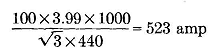
intended to be connected. For example, a 100-hp, 440-volt motor with code letter C would have a starting inrush current of
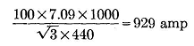
and a 100-hp, 440-volt motor with code letter H would have a starting inrush of
The motor with the code letter H would require reduced-voltage starting on most power systems.
|
|||||||||||||||||||||||||||||||||||||||||||||||||||||||||||||
| Home The Polyphase Induction Motor The Constant-Speed Induction Motor |
|
||||||||||||||||||||||||||||||||||||||||||||||||||||||||||||