| Capacitors, Magnetic Circuits, and Transformers is a free introductory textbook on the physics of capacitors, coils, and transformers. See the editorial for more information.... |

|
Home  Capacitance and Related Effects Polarization and Dielectric Constant Capacitance and Related Effects Polarization and Dielectric Constant |
|||||||||||||


|
  |
||||||||||||
Polarization and Dielectric Constant
Equation 2-33 shows that dielectric materials increase the energy storage capability of a capacitor. This increase results from an increase in the charge on the plates of a capacitor due to charges that are induced by dielectric polarization, a phenomenon first recognized by Faraday.1 Polarization is produced by the orientation, in the direction of the electric field, of electric dipoles in the dielectric material. An electric dipole consists, in effect, of two equal charges of opposite polarity separated from each other by a small distance. Consider the parallel conducting plates, in Fig. 2-21(a), separated from each other by a distance d in vacuum. A potential difference of V volts is
maintained between the plates and the free charges indicated by the plus signs and minus signs are produced on the positive and negative plates respectively. The electric field is uniform and in the direction indicated in the region between plates away from the edges. At the edges there is a fringing of the electric flux. The electric field intensity between plates away from the edges is
The electric flux density in this region is also uniform and is expressed by
Suppose that the voltage across the plates is maintained at its former value V and that the space between plates is filled with a dielectric material up to but not beyond the edges of the plates. The free charges on the plates will be the same as before since there is no change in the fringing of the field with the dielectric that fills the space between plates. However, the electric dipoles will tend to align themselves in the direction of the electric field as indicated schematically in Fig. 2-21(b). With such an alignment the electric field intensity in the regions between the aligned dipoles is increased and coulomb forces produced by the dipoles nearest the plates induce the bound charge marked [+] and [-]. Thus the total charge on the plates has increased from a value q in Fig. 2-21(a) to one of q' in Fig. 2-21(b). This increased value of charge is the sum of the free charges and the charges induced by the dipoles. The flux density in the region between the plates has increased in the same proportion and can be expressed by
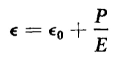
The term P in Eq. 2-70 is defined as the dielectric polarization because it is the increase in flux density produced by the alignment of the dipoles in the dielectric material. The dielectric constant ε is the ratio of electric flux density to electric field intensity. Thus, if Eq. 2-70 is divided by the electric field intensity E the expression for the dielectric constant is
The expression for the relative dielectric constant is obtained by dividing Eq. 2-71 by ε0 as follows
|
|||||||||||||
| Home Capacitance and Related Effects Polarization and Dielectric Constant |
|
||||||||||||


Last Update: 2011-02-16