| Capacitors, Magnetic Circuits, and Transformers is a free introductory textbook on the physics of capacitors, coils, and transformers. See the editorial for more information.... |

|
Home  Capacitance and Related Effects A-C Characteristics of Dielectrics Capacitance and Related Effects A-C Characteristics of Dielectrics |
|||||||||||


|
  |
||||||||||
A-C Characteristics of Dielectrics
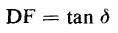
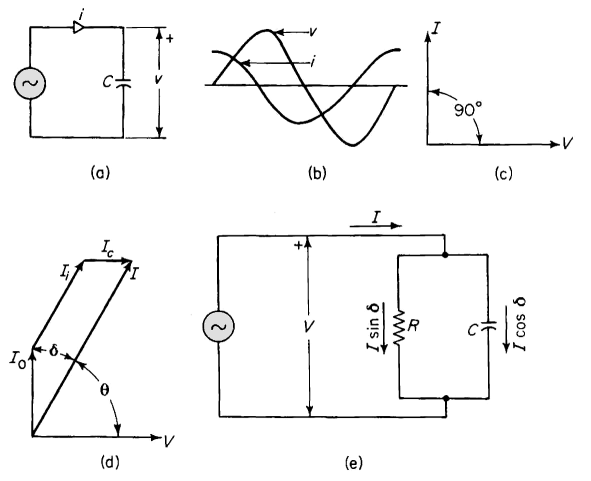
Equations 2-65 and 2-67 show that current in an ideal capacitor [Fig. 2-25(a)] leads the applied voltage, if sinusoidal, by an angle of 90° as shown in Fig. 2-25. In liquid dielectrics such as insulating oils and other liquids used in capacitors, transformers, and high-voltage cables, as well as in solid dielectrics, the current leads the voltage by an angle that is somewhat smaller than 90°. This departure from 90° results from dielectric energy losses that show up in the form of heat. In the case of a-c fields the dipoles undergo rotation, which is opposed, to some extent, by a sort of molecular friction, and as a result the current associated with the charges induced by the dipoles leads the voltage by an angle of less than 90°. Other losses result from conduction currents in the dielectric. The phasor diagram of Fig. 2-25(d) shows the relationships between the components of current resulting from the free charges, induced charges, and conduction in a capacitor with an imperfect dielectric. In Fig. 2-25 let I0 = charging current from the free charge
The current I0 is the current that would result if the dielectric were free space. The dielectric power factor is
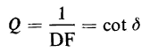
Dissipation factor is a term commonly used in connection with dielectric losses and the symbol for it is DF
At small values of d the difference between the power factor cos Θ or sin δ and the dissipation factor tan δ is negligible. For example when the power factor, i.e., sin δ is 0.1000 the dissipation factor tan δ is 0.1004. The value of dissipation factor is about 0.005 or less for dielectrics used in high-voltage cable, liquid-impregnated capacitors, and other applications where dielectric losses must be kept at low values. The angle δ shown in Fig. 2-25(d) is much larger than is normal for a good dielectric. The quality factor Q is another term used in connection with capacitors; it is the reciprocal of the dissipation factor, i.e.
The equivalent circuit for an imperfect capacitor is shown in Fig, 2-25(e), which shows the loss component of current I tan δ to flow through an equivalent resistance and the out-of-phase current I cot δ to flow through an equivalent ideal capacitance. This equivalent circuit greatly oversimplifies the actual conditions. In a given dielectric the dielectric constant and consequently the capacitance C of Fig. 2-25(e) varies with frequency and temperature. The dielectric losses are also functions of frequency and temperature so that the shunt resistance R is also a variable. Nevertheless, the equivalent circuit of Fig. 2-25(e) is quite useful for certain kinds of analyses.
|
|||||||||||
| Home Capacitance and Related Effects A-C Characteristics of Dielectrics |
|
||||||||||
Last Update: 2011-01-10