| Capacitors, Magnetic Circuits, and Transformers is a free introductory textbook on the physics of capacitors, coils, and transformers. See the editorial for more information.... |

|
Home  The Transformer Voltage Ratio, Current Ratio, and Impedance Ratio Impedance Ratio The Transformer Voltage Ratio, Current Ratio, and Impedance Ratio Impedance Ratio |
|||||||||||||||||||||


|
  |
||||||||||||||||||||
Impedance Ratio
In many problems that involve transformers it is convenient to refer the impedance in one side of the transformer to the other side of the transformer.
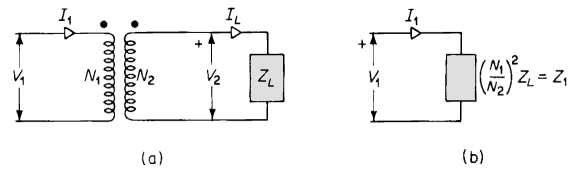
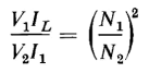
For example, Fig. 6-5(a) shows an ideal transformer with a load impedance of ZL ohms connected across its secondary terminals. The load impedance referred to the primary is the value of impedance that, if connected directly across the source of voltage V1, would draw the same value of current I1 as the transformer with its connected load impedance ZL. This is shown in Fig. 6-5(b). When Eq. 6-14 is divided by Eq. 6-17 the result is
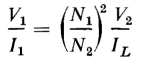
or
But the load impedance is
and an impedance that would draw a current of I1 amp when connected directly across the source of voltage of V1 v must have a value of
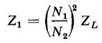
A comparison of Eqs. 6-18, 6-19, and 6-20 shows that
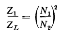
where Z1 is the value of the load impedance referred to the primary of the transformer. The impedance ratio is, therefore
or the square of the turns ratio of the transformer. The turns ratio of a transformer is sometimes represented by the letter a, which means that
and the impedance ratio is
|
|||||||||||||||||||||
| Home The Transformer Voltage Ratio, Current Ratio, and Impedance Ratio Impedance Ratio |
|
||||||||||||||||||||


Last Update: 2011-01-15