| Capacitors, Magnetic Circuits, and Transformers is a free introductory textbook on the physics of capacitors, coils, and transformers. See the editorial for more information.... |
|
Home  The Transformer Autotransformers The Transformer Autotransformers |
|||||||||||||||||||||
| See also: Instrument Transformers | |||||||||||||||||||||


|
  |
||||||||||||||||||||
Autotransformers
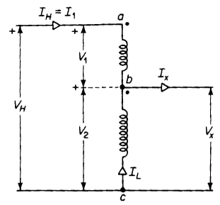
In cases where the ratio of transformation does not differ greatly from unity, and in cases that do not require the secondary winding to be isolated from the primary winding, a great saving in size can be effected by using autotransformers in place of the two-circuit transformers discussed previously in this chapter. An ordinary two-circuit transformer can be converted to an autotransformer by connecting its windings 1 and 2 in series with each other as shown in Fig. 6-18. In the autotransformer of Fig. 6-18, consider winding 1 to be between points a and b and winding 2 to be between points b and c. The voltage VH on the high side of the autotransformer is the phasor sum of the terminal voltages of windings 1 and 2, i.e.
The phase angle between the primary and secondary voltage of a power transformer is small. In the case of the transformer in Example 6-2, the angle between the primary and secondary voltage phasors is smaller than 1°, although phase angles as high as 10° are possible. Nevertheless, it can be assumed for most practical purposes that the arithmetic sum of the voltages V1 and V2 equals the phasor sum, i.e.
In addition, the ratio of the terminal volts V2 and V1 is within a few percent of the turns ratio, as indicated in the transformer of Example 6-2. Hence
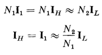
The exciting ampere turns required by the flux in the core is the phasor difference between the ampere turns of the two windings. Generally, in iron-core transformers the exciting current is small in comparison with the rated current. (In the transformer of Example 6-2 the ratio of exciting current to rated current is 1.70 / 62.5 or 2.72 percent.) Then, if the exciting current is neglected, the ampere turns of the two windings must be equal, and we have
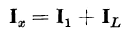
The current Ix, which flows in the low-voltage terminals, is the sum of the secondary current IL and the primary current I1 as shown in Fig. 6-18, so that
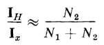
A comparison of Eqs. 6-63 and 6-64 shows that
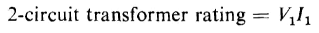
When the ratio of transformation is near unity, the transformer has a much higher rating when operating as an autotransformer than when operating as a 2-circuit transformer. This is shown as follows
Thus, if the voltage rating as a 2-circuit transformer is 2400/240, the volt-ampere rating as a 2640/2400-v autotransformer is eleven times that of the volt-ampere rating as a 2-winding transformer.
|
|||||||||||||||||||||
| Home The Transformer Autotransformers |
|
||||||||||||||||||||


Last Update: 2011-01-13