| Capacitors, Magnetic Circuits, and Transformers is a free introductory textbook on the physics of capacitors, coils, and transformers. See the editorial for more information.... |

|
Home  The Transformer Variable-Frequency Transformers The Transformer Variable-Frequency Transformers |
|||||||||||||||||||||||||||||||


|
  |
||||||||||||||||||||||||||||||
Variable-Frequency Transformers
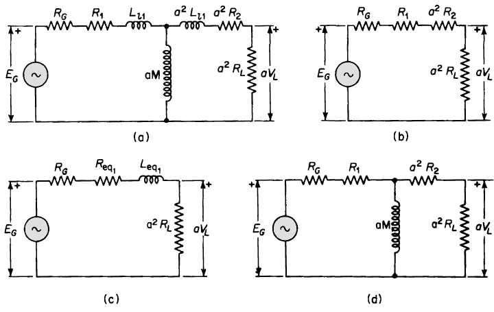
Iron-core transformers are operated over a wide range of audio frequencies in communication circuits such as radio-frequency transmitters, radio receivers, and in conjunction with telephone circuits. Generally, the function of transformers in such arrangements is to couple an audio-frequency source, which may have relatively high impedance, usually in the form of resistance, to a load circuit, which may have a relatively low value of impedance, so as to obtain maximum power transfer or optimum performance. For example, the electronic circuit in a radio receiver may give its optimum performance, from the standpoint of power output, with negligible distortion when feeding into a load impedance of about 4,000 or 5,000 ohms, whereas, the apparent impedance of the load, such as the voice coil of a loud-speaker, is only about 10 ohms. A properly designed transformer, with an impedance ratio of about 400, connected between the electronic circuit and the loud-speaker would assure good performance. Such a transformer is known as an output transformer, and in this case would have a ratio of a = If the ratio and the phase angle between the primary and secondary voltages were unaffected by frequency, signals would be transmitted from the primary of the transformer to the secondary without distortion. This would be an ideal situation. However, the leakage reactance ωLeq increases with frequency and the exciting admittance decreases with increasing frequency. Both of these effects influence the ratio and phase angle. However, in the usual electronic circuit, the transformer leakage impedance is considerably smaller than the resistance of the source and the load, so that the effects of frequency are mitigated by the impedances of the source and the load. The core loss can be neglected in output transformers. The distributed capacitances between the turns and layers of each winding, as well as between windings (and between each winding and case and core) can also usually be neglected. The equivalent circuit shown in Fig. 6-19(a) is based on these considerations and includes, in addition to the transformer leakage impedance and magnetizing inductance, the resistance of the source and the load, all referred to the transformer primary. The circuit of Fig. 6-19(a) is valid throughout the normal range of audio frequencies. Further simplifications in the equivalent circuit are shown in Figs. 6-19(b), 6-19(c), and 6-19(d). Figure 6-19(b) applies to the middle-frequency range. In this range the frequencies are low enough so that the leakage reactance ωLeq1 is negligible in comparison with the resistance of the entire circuit, and at the same time the frequencies are high enough so that the current through the magnetizing reactance ωαM is negligible in relation to the load current. Frequencies of such high values that the leakage reactance ωLeq1 of the transformer becomes appreciable are said to be in the high-frequency range. The equivalent circuit in Fig. 6-19(c) applies to the high-frequency range. Since the current through the magnetizing reactance ωαM is already negligible in the middle-frequency range, it is even smaller proportionately in the high-frequency range and can, therefore, again be neglected. Below the middle range of frequencies lies the low-frequency range in which the magnetizing current through the mutual reactance ωαM becomes appreciable. However, since the frequencies are now below the middle range, the leakage reactance ωLeq1 is again negligible and the equivalent circuit of Fig. 6-19(d) now applies.
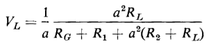
Signals at frequencies within the middle range are all transmitted at about the same voltage ratio and with negligible phase shift. This means that such signals undergo negligible distortion when transmitted through the output transformer. From Fig. 6-19(b) the load voltage is
and the voltage ratio can be abbreviated to
in which
and
The frequency components of signals, which are in the high-frequency range, are not all transmitted to the load at the same voltage ratio nor at the same phase angle between the generated voltage and the load voltage. The higher the frequency of a component or harmonic, the greater is the attenuation, i.e., the smaller is the voltage ratio VL/EG and the greater is the phase shift between the voltages VL and EG. As a result, a signal, which is a composite of a number of frequencies some of which are in the high-frequency range, undergoes distortion because of the transformer leakage inductance Leq1 The voltage ratio and phase angle for the high-frequency range are expressed, on the basis of Fig. 6-19(c), by
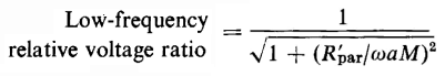
The ratio of transformation in the low-frequency range decreases with decreasing frequency. The phase shift is opposite that of the high-frequency range, increasing in the opposite direction as the frequency decreases. On the basis of the equivalent circuit in Fig. 6-19(d), the voltage ratio at low frequencies is
where
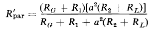
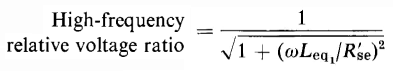
Distortion results in the low-frequency range because the signal strength decreases with decreasing frequency and the phase shift increases with decreasing frequency. Since the signals in the middle-frequency range undergo negligible distortion, the voltage ratio in that range may be considered a norm with which the voltage ratios in the other two frequency ranges are compared. Hence, division of the amplitudes in Eq. 6-73 by that in Eq. 6-72 yields
and when Eq. 6-74 is divided by Eq. 6-72, the result is
The power output of the circuit is
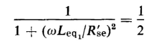
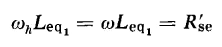
and the frequencies at which the power output is one-half that in the middle range for a given value of EG are called the half-power points. At these frequencies the square of the relative voltage ratio equals 1/2. The high half-power frequency fh is found by equating the square of the right-hand side of Eq. 6-75 to 1/2 as follows
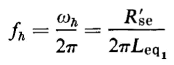
from which we get
and
Similarly, the half-power frequency for the low-frequency range is found to be
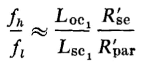
It is customary in practice to take the value of the short-circuit self-inductance Lsc1 as Leq1 in Eq. 6-78 and the open-circuit inductance Loc1 as αM in Eq. 6-79 since Loc1 = Ll1 + αM and the primary leakage inductance Ll1 is small in comparison with the open-circuit inductance Loc1 . Equations 6-78 and 6-79 can therefore be approximated to
and
The following ratio is a measure of the width of the band between the half-power frequencies
The geometric mean frequency is
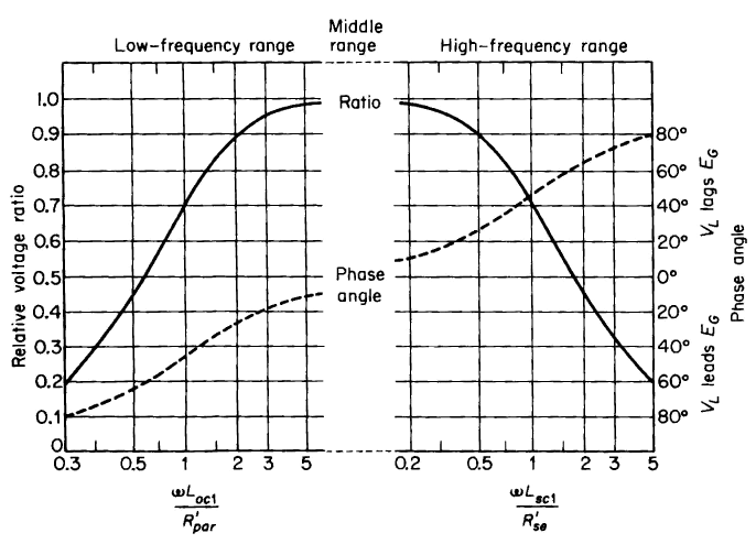
A graphical representation of the frequency and phase characteristics of output transformers is shown in Fig. 6-20.
The geometric mean frequency for output transformers used in radio receivers is roughly 500 cps. The greater the band width for the proper value of geometric mean frequency, the smaller is the distortion of a signal that contains harmonics throughout the audio-frequency spectrum. This means that a high value of open-circuit inductance Loc1 and low value of short-circuit inductance Lsc1, i.e., tight magnetic coupling between windings, is desirable. It is difficult to increase the band width of an audio transformer with a core of a given size and configuration. The open-circuit inductance Loc1 can be increased by increasing the number of turns in the windings, which means going to a smaller wire size and, therefore, an increase in the resistance. In addition, increasing the turns also increases the short-circuit inductance Lsc1 correspondingly. Hence, the band width remains about the same, as is evident from Eq. 6-82. However, the geometric mean frequency would increase, which means a shift in the band between the half-power frequencies such as to produce a reduction in both the lower and upper half-power frequencies. The upper half-power frequency can be increased by decreasing the short-circuit inductance Lsc1, which calls for an increase in the tightness of the coupling between the windings. This also increases the band width. However, an increase in the open-circuit inductance Loc1 calls for an increase in the number of turns or in the size of the core. In any event, if Loc1 is to be increased, without a corresponding increase in the resistance, the size of the transformer must be increased. Perfect reproduction of the signal would require an output transformer of infinite size. However, economic considerations limit the size to relatively small values, and the resulting distortion in the wave form can be tolerated because of the insensitivity of the human ear to moderate changes in the relative amplitudes of the harmonic components of the signal. In addition, the human ear is unable to detect changes in the relative phase relations over a considerable range.
|
|||||||||||||||||||||||||||||||
| Home The Transformer Variable-Frequency Transformers |
|
||||||||||||||||||||||||||||||
 = 20. Iron-core transformers are also used to isolate one audio-frequency circuit from another so as to prevent the d-c component of current in one of these circuits from flowing into the other circuit. Although the wave forms of speech, music, and other sounds are very complicated, the audio-frequency range is considered to extend from about 16 to 20,000 cps, which are the effective limits of audibility for a steady-state sinusoidal signal.


Last Update: 2011-02-16