| Radio Antenna Engineering is a free introductory textbook on radio antennas and their applications. See the editorial for more information.... |

|
Home  Low-Frequency Antennas Multiple Tuning Multiple Tuning for Impedance Transformation Low-Frequency Antennas Multiple Tuning Multiple Tuning for Impedance Transformation |
||||||||||


|
  |
|||||||||
|
Multiple Tuning for Impedance TransformationAuthor: Edmund A. Laport One of the characteristics of multiple tuning has been shown to be the transformation of impedance at the feed point when power is fed into only one of several down leads. Advantage of this principle can be taken in some cases to obtain a more favorable input impedance, principally an increase in the input resistance, for coupling and matching purposes.
The technique can be applied in the following manner:
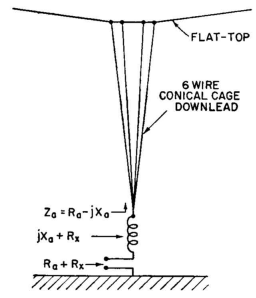
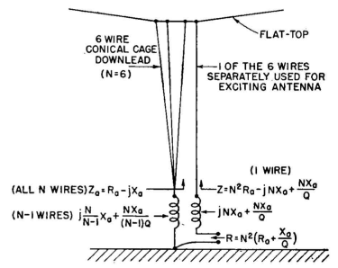
By the multiple-tuning technique, we can produce a practical transformation ratio in the antenna itself and therefore simplify the coupling problem. The antenna can be fed through any one of the six wires. This will multiply the input resistance by 62 = 36. At this stage it must be remembered that the quantity multiplied will be the total antenna resistance, which includes the resistance of the load coil as well as that of the antenna itself. The resistance of the antenna, excluding the load coil, has been given as 3 ohms. The load coil Q must now be estimated. Let it be arbitrarily assumed, for the frequency and anticipated design, to be 500.1 The load-coil resistance will be 320/500, or 0.64, ohm. The total resistance will then be 3.64 ohms. Now, if power is fed into one of the six wires, the input resistance will be 3.64 X 36 = 131 ohms. This is now a value of resistance that can be a direct termination for certain types of unbalanced open-wire transmission line after tuning out the input reactance with a series inductance. The total tuning reactance required is 320 ohms. This can be lumped all in one coil; or each of the six wires could be kept separated and a series reactance of 6·320 = 1,920 ohms used in each wire. If the coil Q were the same as for one lumped inductance, the same result would be obtained. In the example, where we feed into one of the six wires, we can use a load coil with a reactance of 1,920 ohms. Since the other five wires are connected together, a single load coil of reactance 1,920/5 = 384 ohms can be used. The circuit is now as shown in Fig. 1.10. The overall performance of the system is identical with single series tuning except that the input impedance has been transformed from 3.64-j320 ohms to 131-j1,920 ohms. The reactance is tuned out with the second coil of 1,920 ohms, so that the actual feed-point impedance is 131 ohms resistive. This may be used as a direct termination for a transmission line having a characteristic impedance of approximately 130 ohms. A coupling network is thus eliminated in an efficient and inexpensive way. The transformation ratio can be varied by using different numbers of down-lead wires in parallel and by changing the ratio of currents in the wires. The foregoing example assumed a circular disposition of the wires in which the antenna current was uniformly, divided among them. Other system cross sections can be used which will provide unequal division of currents to modify the transformation ratio, more or less at will. The system efficiency, the total antenna current, the potentials and bandwidth of the entire radiating system are the same as if simple single tuning had been used.
|
||||||||||
| Home Low-Frequency Antennas Multiple Tuning Multiple Tuning for Impedance Transformation |
|
|||||||||
Last Update: 2011-03-19