| Radio Antenna Engineering is a free introductory textbook on radio antennas and their applications. See the editorial for more information.... |

|
Home  Low-Frequency Antennas Antenna Potential Low-Frequency Antennas Antenna Potential |
||


|
  |
|
|
Antenna PotentialAuthor: Edmund A. Laport
 ). ).
Low-frequency antennas are commonly fed in series between the down lead and ground. At this point the antenna resistance Ra includes those components of resistance due to radiation, insulation losses, corona losses, conductor heating, and ground loss. If the antenna tuning inductance is included as part of the antenna instead of part of the transmitter, its resistance is also included in the system resistance. Then, for a power input to the system of Wa (watts), the antenna current at the feed point will be
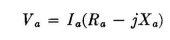
The feed-point potential at the bottom of the down lead will be where Xa is the antenna reactance at the working frequency.
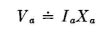
In general, Xa is very large with respect to Ra so that the antenna potential becomes simply
For typical top-loaded antennas having an electrical length of less than 20 degrees at the working frequency, the antenna potential is identical within 3 to 5 percent over the entire antenna. For any practical design purposes, one may arbitrarily assume that the maximum potential existing on any ordinary low-frequency-antenna design due to potential build-up from its standing-wave potential-distribution pattern will not exceed
For practical purposes it is quite sufficient simply to add a few percent to the value of the product IaXa. The potential need be known only approximately in ordinary cases in order to estimate the insulation requirements of the system and the potential gradients at critical points. The gradients must be below those which produce corona and pluming (standing arcs) at the altitude of the site. The conductors of the antenna must be of sufficient diameter and their physical arrangement planned so as to keep all potential gradients below critical values. For high-power systems, this becomes a major engineering problem, necessitating the use of large and heavy conductors with their attendant mechanical and economic problems. The critical corona-producing gradients vary with the atmospheric pressure, the turbulence of the air, and the frequency. Another important factor is the energy of the system, which may be more than sufficient to sustain large and destructive plumes as well as self-propagating arcs that produce actual flashovers to ground. Therefore high-potential engineering on high-power antenna systems has two distinct phases - that of not overstressing the air dielectric around the conductors and metallic parts, and that of the selection of solid insulation for isolating the antenna conductors from ground and supporting structures. It is evident from the direct proportionality between antenna potential and antenna reactance, all other factors remaining constant, that all the techniques mentioned in Sec. 1.8 for reducing reactance will minimize the antenna potential for any given power input. Such techniques therefore raise the maximum power-handling capability of the system. They also tend to increase the bandwidth of the system as explained in Sec. 1.9. The potential gradients to be expected in various parts of a multiwire antenna are at times impossible to compute accurately. Satisfactory approximations for engineering purposes can usually be made by simple methods. The computation starts with the value of potential existing at the surface of the conductor. This is determined from a measurement of the antenna impedance and the antenna current for the power input to the antenna and from the estimated build-up of potential above the feed point, which depends upon the configuration and the potential distribution. Several wires in parallel or in close proximity at the same potential reduce the potential gradients as compared with a single isolated wire at the same potential. A single wire that is separated from ground, supporting towers, and other wires of the system by a distance of a few hundred wire diameters can be assumed to have a strictly radial electrical field at the wire surface. The equipotential surfaces close to it will be concentric with the axis. To solve for the potential gradient near such a wire, we may assume its image charge to be uniformly distributed over an imaginary cylindrical surface at a considerable distance like the outer conductor of a concentric transmission line. We can apply the principles of a concentric transmission line and consider that the isolated wire is the central conductor of a concentric transmission line having a characteristic impedance of large value, say 300 ohms or more. This requires that the outer concentric conductor have a very large diameter. In this analogy, the potential gradients in the vicinity of the antenna wire will approximate, with acceptable accuracy, those which would exist for the same size wire at the same potential used as the central conductor of this equivalent concentric line. The maximum safe operating potential for an antenna conductor can be computed from the information given in Sec. 4.9. When there are other wires at the same potential in the vicinity of a wire, as when there are several wires in parallel, the maximum safe operating potential for the same wire size is increased somewhat. When the wire is in the vicinity of grounded structures or wires of opposite potential, the maximum safe operating potential is reduced. High localized potential gradients, which are incipient sources of weakness, can sometimes be reduced by applying corona shields or insulated controls. Corona shields reduce local potentials by distributing the electric charge over a larger area and thus reduce the electric-flux density below critical values that produce ionization. The insulated control is used for the same purpose, but it functions in a different manner. It reduces localized gradients by placing dielectric material in the high-intensity electrical field and smooths the discontinuity between metallic surfaces with a dielectric constant of infinity and air which has a dielectric constant of about 1.0. The layer of dielectric material acts as a corona shield. Many localized weak points in a low-frequency antenna system can be corrected by the use of insulated controls. For example, the corona limit for a wire system is raised if the wires are coated with certain insulating varnishes with a high dielectric constant. The varnish also reduces the rate of corrosion of the conductors. A projection that causes corona can often be neutralized by attaching a mass of insulating material in the high-strength field, but in such a way that small dead-air spaces are completely absent; otherwise there may be ionization in the dead-air regions. Plastic as well as solid dielectrics are useful in many borderline brushing problems. Plastics are usually more convenient than corona shields made of metal. An insulated control is usually more effective with drip water than a metallic shield where the drip water may be the source of brushing or pluming from the metal surfaces. When it is desired to increase transmitter power at an existing low-frequency station, it may be found that some modifications are needed to make the antenna safely withstand the increased potential. In most cases these problems will be localized. Special measures applied to the weak points, as just mentioned, will often remove the limitations at relatively small expense. The indication of an optimum antenna design is when the potentials are limited by corona or pluming on the linear conductors throughout the system and there are no local weak spots. It is necessary then only to ensure that the limiting potentials are well above the operating values.
|
||
| Home Low-Frequency Antennas Antenna Potential |
|
|


Last Update: 2011-03-19