| Radio Antenna Engineering is a free introductory textbook on radio antennas and their applications. See the editorial for more information.... |

|
Home  Low-Frequency Antennas Low-frequency Ground Systems Radial-buried-wire Ground System Low-Frequency Antennas Low-frequency Ground Systems Radial-buried-wire Ground System |
|||||


|
  |
||||
|
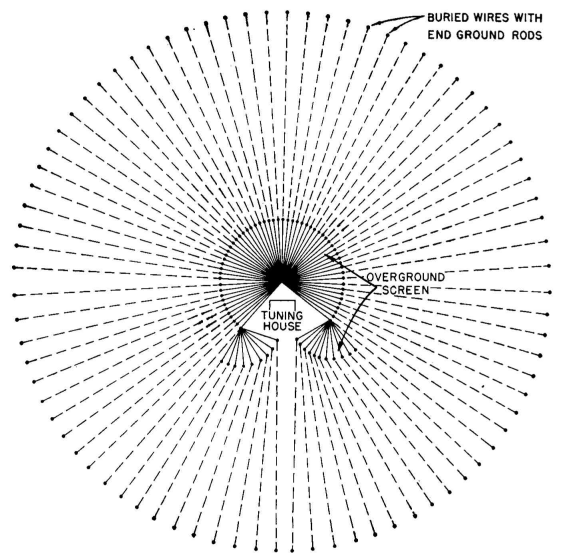
Radial-buried-wire Ground SystemAuthor: Edmund A. Laport The radial-buried-wire system is similar to that used at broadcast frequencies (see Sec. 2.5) where from 15 to 150 radial wires, centered at the antenna base, are buried in the soil. Because of the relatively great conductivity of the wires with respect to the soil, there is a tendency for the current in the soil to be diffracted into the lower resistance paths formed by the wires. The earth currents are at their maximum density at the surface of the ground where the wires are buried so that a substantial portion of the ground current is conducted by the radial wires if they are sufficiently long and sufficiently numerous. But since it is seldom convenient to use electrically long radial wires, a considerable loss may occur in the ground beyond the limits of the buried wires. A considerable loss can also occur because of the deep currents flowing beneath the buried wires, especially at points of concentrated collection such as the base of the antenna. There are several ways in which a ground system can be designed to minimize current densities at low frequencies. 1. Ground rods can be attached at the ends of the radials to intercept as much current as possible vertically at the periphery of the system. Ideally, the ground rods should reach down to the depth corresponding to the skin thickness for the soil conductivity and the operating frequency. This is not usually practical, but it is desirable to use the longest available ground rods. 2. The ground wires may be brought out of and above the surface of the soil at some distance from the antenna base. This requires the deep currents to rise to the surface uniformly at a distance sufficient to prevent excessive concentration at the circle of collecting points.
It is also beneficial to employ ground rods at the point where the radials emerge from the ground. The ground rods should be driven at an angle of 45 degrees toward the center of the system. The inner ground rods, driven in at this angle, reduce still further the concentration of ground currents coming up from below. 3. The radials that emerge and come to the base of the antenna above ground also form an electrostatic ground screen to shield the ground from the intense electric field near the base of the antenna. At this point the antenna potential is high, and the ground screen prevents large dielectric loss in the soil. The exposed portions of the radials are insulated from ground at all points after they emerge from the ground. The exposed portion of the radials should be of the order of 1 electrical degree at least.
4. The length of the buried radials should be made as great as land and budget will permit. The number of radials used should also be as large as budget will permit, up to a maximum of 150 or 180. 5. There should be no closed conductive loops in the ground system in which eddy currents can circulate to increase copper loss. 6. The size of the wire used will depend upon the amount of current collected by each wire for the power and antenna used, taking the precaution to avoid excessive copper loss. This is a factor of great importance where large antenna currents are involved.
|
|||||
| Home Low-Frequency Antennas Low-frequency Ground Systems Radial-buried-wire Ground System |
|
||||

Last Update: 2011-03-19