| Radio Antenna Engineering is a free introductory textbook on radio antennas and their applications. See the editorial for more information.... |

|
Home  Low-Frequency Antennas Low-frequency Ground Systems Counterpoise Low-Frequency Antennas Low-frequency Ground Systems Counterpoise |
||||||||||||


|
  |
|||||||||||
|
CounterpoiseAuthor: Edmund A. Laport
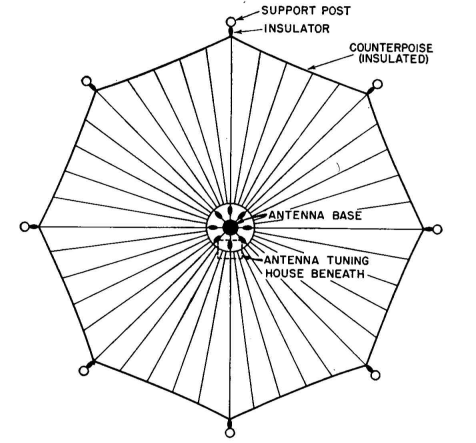
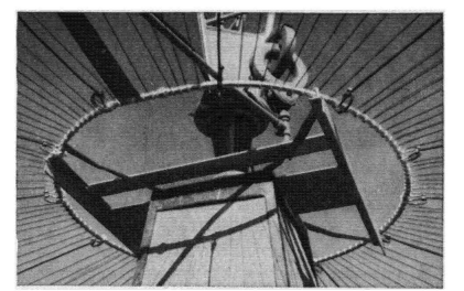
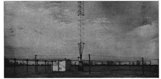
All three of these ground systems require exposed over-ground wires near the antenna base. The buried radial ground system with the wires brought above ground near the antenna is possibly the best choice at stations where there is ample land for an extensive buried-wire system. In this system, the over-ground wires are not dangerous since they are at ground potential. The buried radial system accomplishes current-density reduction and decreases ground losses out to the distance of the buried radials. The over-ground portion forms an excellent ground screen as well. In restricted areas, the star system seems to offer the best possibility of obtaining low ground resistance without the inconvenience and exposed potentials of the counterpoise. However, if the disadvantages of the counterpoise can be tolerated, it may be superior to the star system for low ground resistance. Figures 1.15 and 1.16 show useful details of counterpoise construction. 1
These comparisons are not to be regarded as absolute, for they have not been proved quantitatively over a sufficient range of conditions to be considered as fact. They are the author's opinion from the information at his disposal. The soil conductivity and the frequency for any particular case may modify the controlling factors sufficiently to affect the final choice. For frequencies from 15 kilocycles to 500 kilocycles and soil conductivities from 10-14 to 5,000·10-14 electromagnetic unit (sea water) the conditions vary a great deal. The depth of penetration of ground currents at the low frequencies (see Appendix II) makes it important to consider the nature of the subsoil to the depth known as the "skin thickness." The search for a station site should include an examination of the subsoil characteristics with the purpose of obtaining soil of best available conductivity to a sufficient depth.
A thin covering of good-conductivity topsoil overlying a base of poor conductivity is usually a poor location for a low-frequency station.
|
||||||||||||
| Home Low-Frequency Antennas Low-frequency Ground Systems Counterpoise |
|
|||||||||||
Last Update: 2011-03-19