| Radio Antenna Engineering is a free introductory textbook on radio antennas and their applications. See the editorial for more information.... |

|
Home  Medium-frequency Broadcast Antennas Directive Antennas Producing Symmetrical Multiple-null Patterns Medium-frequency Broadcast Antennas Directive Antennas Producing Symmetrical Multiple-null Patterns |
||||||||||||||||||||||||||||||||||||||||||||||||||||||||||||||||||||||||||||||||||||||||||||||


|
  |
|||||||||||||||||||||||||||||||||||||||||||||||||||||||||||||||||||||||||||||||||||||||||||||
|
Producing Symmetrical Multiple-null PatternsAuthor: Edmund A. Laport
A great variety of symmetrical patterns having multiple nulls (or minimums) with a linear array of three radiators can be derived by the following simple method, illustrated by a random example.
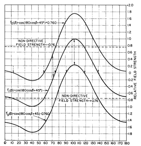
We take the pair of radiators S=360 degrees, φ = 90 degrees, calculate its pattern in the usual way, and tabulate the values in Table 2.14. In the two right-hand columns we have added the field produced by a single nondirective radiator located at the center of the pair. We have chosen a relative field strength of +0.76 to obtain f2( β) and -0.76 to obtain f3(β).
These three patterns are plotted in rectangular coordinates in Fig. 2.47 for clarity. It can be seen in this way that the addition of the fields from a nondirective source at the center of the pair simply "biases" the zero line of the pattern upward for a negative polarity of the center radiator field and downward for a positive. The intensity of the central source adjusts the angles at which the nulls occur. We need only have plotted f1( β) and moved the axis to positions shown by the dotted lines.
In exploring for such a solution, one can study the polar patterns for various pairs, marking the polarity of the lobes of these patterns (if not initially so marked) and then drawing circles to represent the central radiator pattern with an assigned polarity of + or -. From these directive and nondirective patterns, one can visualize qualitatively the locations of nulls (the intersections of the circle with the lobes of opposite polarity) and the algebraic sum of the two, between nulls. After so determining in a rough way a satisfactory starting point, quantitative computations are made. The problem of bringing two or more nulls at correct angles with a satisfactory pattern otherwise cannot be solved directly but must be approached by successive trials.
Rectangular coordinates are the most convenient for this purpose if graphical computation is used. Anyone having frequently to make such calculations would have a large number of the pair patterns predrawn in rectangular coordinates and would use a transparent straightedge over the patterns until a desired choice is found. The radiation pattern for this kind of array is obtained by the algebraic additions of the pair pattern with that of the constant value contributed by the central radiator. However, when it comes to determining the phase of the current in the central radiator with respect to currents in the pair, the central-radiator current must always have a phase that is midway between the phases of the currents in the outer radiators. We may call this "mid-phasing". If in this example we refer all space and phase relations to the center of the array, the phases of the currents in the three radiators will have to be 45, 0, and -45 degrees; or taking one end radiator as reference, the phases must be 0, -45, and -90 degrees in succession. The current ratio for the central radiator with respect to the pair, and therefore the division of power between them, must be separately computed, taking into account the mutual impedances and therefore the gain of the pair as compared with the single central radiator.
|
||||||||||||||||||||||||||||||||||||||||||||||||||||||||||||||||||||||||||||||||||||||||||||||
| Home Medium-frequency Broadcast Antennas Directive Antennas Producing Symmetrical Multiple-null Patterns |
|
|||||||||||||||||||||||||||||||||||||||||||||||||||||||||||||||||||||||||||||||||||||||||||||
Last Update: 2011-03-19