| Radio Antenna Engineering is a free introductory textbook on radio antennas and their applications. See the editorial for more information.... |

|
Home  High-frequency Antennas Factors Affecting Signal Intelligibility Diversity Reception High-frequency Antennas Factors Affecting Signal Intelligibility Diversity Reception |
||||||||||


|
  |
|||||||||
|
Diversity ReceptionAuthor: Edmund A. Laport Systematic measurements have been made from time to time under many different operating conditions to determine the quantitative value of diversity reception. It has been known for many years, from the works of Beverage and Peterson, that two-set and three-set diversity reception gives greatly improved circuit performance in the presence of the various factors encountered in longdistance high-frequency communication. Measurements made in 1949 using new techniques have shown for the first time that the "gain" in circuit performance due to diversity reception varies with the degree of reliability of the circuit.
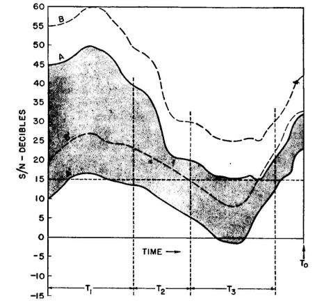
Figure 3.11 shows a set of communication conditions which are arbitrary but which represent in general what occurs on every path. This example may apply to radio communication in general, but for the present it will refer to high-frequency communication. The signal-to-noise ratio (S/N) in decibels is plotted against time for a period of time TV This epoch may be a minute, an hour, a day, a season, or a sunspot cycle, according to the case. The short-period signal-to-noise variations lie between curves AA' for a power P1 transmitted, and over a longer period the envelope for the instantaneous variations goes through a wide range of variations. These variations may be due to any or all of the causes of signal variation by propagation, by the antennas, and to all the changes in received noise. Let it be assumed that a simple amplitude-modulated telephone service is desired, the lower limit of signal-to-noise ratio for satisfactory communication being 15 decibels. That portion of the time when the signal is below this level may be regarded as lost time. In the epoch T1 the range of variation of signal-to-noise is almost all above the working limit, and those values of A' which are below the 15-decibel value are probably of very short duration (sometimes of seconds only) and represent a very small percentage of the time. This epoch represents the conditions for a good circuit.
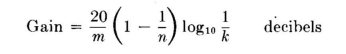
In the epoch T2 the circuit begins to be marginal because a substantial percentage of the time the signal is below working limits. This condition may be acceptable for an intermittent service by taking advantage of those times when communication can be supported. However, for a commercial service this period of time would be a difficult one. Finally, the epoch T3 represents completely unworkable conditions because S/N is greater than the required 15 decibels only a very small percentage of the time. The curves BB' represent the same conditions but with a 10-decibel improvement in signal-to-noise ratio. This improvement may of course be obtained by increasing transmitter power 10 times or by somehow reducing noise pickup by 10 decibels. During the times when communication is marginal or impractical, it can be seen that a power increase of less than 10 decibels makes only a trivial improvement in circuit performance. Even though any increase in transmitter power will increase S/N, it is in fact necessary to employ substantial power increases to make a worth-while improvement in circuit performance. If we assume that the circuit is properly engineered with regard to antennas, working frequencies, etc., and the final problem is that of the transmitter power to be used, the power required will be determined entirely by the desired circuit reliability in terms of the percentage of the time the circuit is workable in relation to the times when the service is needed. If a "solid" circuit is required, the power to be used must be sufficient at all times to deliver a signal that will override ambient noise by the amount dictated for the type of emission employed. Amplitude-modulation telephony will require the 15-decibel value that has been used in the above discussion. Frequency-shift teleprinter service may be workable when S/N is as low as 2 or 3, and manual Morse operation with skilled operators may be sufficiently workable at -10 decibels. In any event, the amount of power used at the transmitter may be below the minimum mentioned for solid service only by forfeiting reliability. In choosing a lower power for economic reasons (and this is typical in general in practical communication economics) advantage can often be taken of regular periods of good propagation and low noise for traffic clearance, assuming of course, a tolerable time distribution of these factors. In practice, this general situation prevails, except that the range of values of S/N may be much greater and perhaps even less than those shown in Fig. 3.11. The range of values used in this example are representative of a fairly good circuit if the epoch T0 is sufficiently long to embrace the full range of variation encountered on a given circuit. The range of instantaneous variation between AA' (or BB'), if due mainly to variations in received signal (if noise is relatively constant), can often be reduced by better accommodation of antenna radiation characteristics to the propagation conditions. When this can be done, it is actually as good as an increase in transmitter power because the lower limit of the signal envelope A' will be higher, and at the same time the upper limit of variation A is reduced. If it were possible to eliminate instantaneous wide-range variations entirely, S/N would then lie midway between A and A'. This desirable condition is not likely to be achievable, but before increasing transmitter power it may be worth while to see what can be done to decrease the range of variation between A and A'. Any method that will reduce multipath propagation will usually decrease the range of signal variation from moment to moment. This will also increase signal intelligibility. However, if variation in noise level is the dominant cause of the variation in S/N, and if directive discrimination against noise is impractical, the only course left to improve the circuit is by a sufficient increase in transmitter power. This latter condition is that prevailing generally in high-frequency broadcasting service, where there is no opportunity to modify the conditions surrounding the receivers. When the conditions represented in Fig. 3.11 typify short-time variations (seconds or perhaps minutes), it is evident that diversity reception could be employed to equalize them, provided that the same variations occurred at random on a second or third receiving channel.1 In such circumstances there is the probability that one diversity channel would provide a satisfactory signal-to-noise ratio at the instant that another experiences a fade-out. The combined output of the diversity receiver would therefore be relatively uniform, and the percentage of total time that the overall signal-to-noise ratio is below threshold value is reduced. The reduction of the time-loss factor due to diversity reception is a system gain equivalent to the power gain that would have to be used at the transmitter to realize the same time loss with a nondiversity system. This gain has been expressed as2
where m is an empirical factor of a nominal value of 2 but which may vary from 1 to 2.5 in practice, n is the number of diversity sets or channels used, and k is the permissible time-loss factor for the system.
|
||||||||||
| Home High-frequency Antennas Factors Affecting Signal Intelligibility Diversity Reception |
|
|||||||||
Last Update: 2011-03-19