| Radio Antenna Engineering is a free introductory textbook on radio antennas and their applications. See the editorial for more information.... |

|
Home  Radio-frequency Transmission Lines Radio-frequency Currents in Linear Conductors Important Transmission-line Equations Radio-frequency Transmission Lines Radio-frequency Currents in Linear Conductors Important Transmission-line Equations |
||||||||||||||||||||||||||||||||||||||||||||||||||||


|
  |
|||||||||||||||||||||||||||||||||||||||||||||||||||
|
Important Transmission-line EquationsAuthor: Edmund A. Laport
In general
At radio frequencies, when ω becomes very large with respect to other factors
When the field of the transmission line is entirely within an isotropic dielectric medium having an inductivity, or dielectric constant, ,
The propagation constant y is in general complex;
At radio frequencies and with lossless lines, 7 becomes essentially a phase angle per unit length.
The velocity of propagation of transverse electromagnetic waves in systems of parallel linear conductors with air dielectric is equal to c, which is the velocity of light in free space (3·108 meters per second).
For a line in an isotropic dielectric ε, the velocity of propagation is
When a radio-frequency line of length βl degrees (or radians) is terminated in a complex impedance Zt the input impedance Zin is, in general, complex, in accordance with the equation
When Zt <> Z0, there is reflection from the termination. The reflection factor is, in general, complex, and is specified as follows:
When Zt = 0 (short circuit),
When Zt =
For a line of length βl = π radians = 180 degrees (one-half wavelength) also
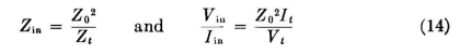
For a line of length βl = π/2 = 90 degrees (one-quarter wavelength)
This is an impedance-inverting circuit with a 90-degree change in relative phase between input and output currents and potentials. When βl = 45 degrees (one-eighth wavelength) and Zt = Rt + j0,
and in general |Zin| = |Z0| for all values of Rt, positive and negative, from 0 to The standing-wave ratio Q on a transmission line increases with increasing inequality between Zt and Z0 both in phase and in magnitude.
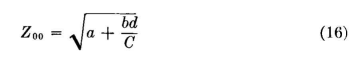
This equation for Q is useful when transmission lines are used as high-Q resonant circuits. When a section of transmission line is used as a transformer to match an impedance Zt = Rt ± jXt with another impedance Zin = Rin ± jXin, the characteristic impedance Z00 of the transforming section is
and its electrical length must be
in which
In all the preceding equations the following symbols apply:
|
||||||||||||||||||||||||||||||||||||||||||||||||||||
| Home Radio-frequency Transmission Lines Radio-frequency Currents in Linear Conductors Important Transmission-line Equations |
|
|||||||||||||||||||||||||||||||||||||||||||||||||||


 (open circuit),


Last Update: 2011-03-19