| Radio Antenna Engineering is a free introductory textbook on radio antennas and their applications. See the editorial for more information.... |
|
Home  Radio-frequency Transmission Lines Useful Transmission-line Configurations Introduction Radio-frequency Transmission Lines Useful Transmission-line Configurations Introduction |
||||||||||||||||||||||


|
  |
|||||||||||||||||||||
|
Useful Transmission-line ConfigurationsAuthor: Edmund A. Laport
The equations throughout this section will employ the following symbols:
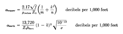
The attenuation of a transmission line without ground-return currents is composed of a component αcopper, due to loss in all the conductors, and αi, due to loss in the insulation. In a line having all or part of the return current in the ground, there is an additional component αearth due to loss in the ground. The total attenuation atotol is the sum of copper, αearth, and αi. In equations for a which include only αcopper and αearth the symbol αce will be used. The larger the number of wires used in parallel, the higher the power capacity of the line in general. The charge density per unit surface of the wire and the potential gradients are thus reduced. In certain configurations, the charges on all the wires at the same potential are not equal, and the formulation must then include the solution for the relative charge distribution. This is set out in a separate formula so that the designer will know its value. In unbalanced open-wire lines, there is a division of charges between the grounded wires and those induced in the earth under the line. In dynamic operation the line currents and the earth-return currents are in the same proportion as the electrostatic charges. The ratio of the total return current in the grounded wires to the total current in the high-potential wires is an indication of the relative merit of the configuration. For example, when k = 0.842, it means that 84.2 percent of the return current is in the grounded wires and that the remainder, 15.8 percent. returns in the earth. It is desirable to design for the higher values of k because the smaller the earth-return current, the lower the attenuation and the smaller the radiation from the line.28 As k approaches unity, there is no more radiation from an unbalanced line than from a balanced line of similar sectional dimensions. Unbalanced lines are especially convenient for feeding the types of antennas used in the low and medium radio frequencies, which typically have one side of the circuit connected to ground. An open-wire unbalanced line radiates more than an enclosed line or an open-wire balanced line. The amount of radiation is very small with lines that have large values of k. From a loss standpoint, radiation loss is negligible in proportion to all other losses in the line. A well-designed open-wire unbalanced feeder with a high value of k can always be used without hesitation with nondirective antennas. They have also been used successfully with directive antennas when the ratio of maximum to minimum field strengths is of moderate value. In the formulas that follow all mechanical dimensions are in the same units, unless subscripted to indicate otherwise. All attenuations are formulated in decibels per 1,000 feet of feeder when working into a perfectly matched termination for a frequency / in megacycles. It is assumed that there are no buried ground wires in the region where the earth-return currents for the line flow. Buried ground wires parallel to and under the line produce an empirical value for a that is much greater than for natural earth constants. This reduces attenuation. The attenuation formulas do not include insulation losses. In many cases insulation losses are negligibly low, but in any case they are empirical and not susceptible to formulation. The losses in a feeder are the sum of the copper loss, earth return loss, insulation loss, and loss due to direct radiation. Radiation loss from a matched feeder is usually so small that it is negligible for carefully designed systems, and it is always very small with respect to all other losses for almost any type of feeder. Insulation loss in a well-designed system is also a minor quantity except in long feeders working in the high-frequency range, where insulation loss on a two-wire balanced line may exceed one-half as much as the copper loss. The principal losses in an unbalanced open-wire line are copper loss and ground-return loss. Brown28 has shown that the attenuation factors due to copper and earth-return losses can be formulated as shown here, where m is the number of high-potential wires in parallel and n the number of grounded wires:
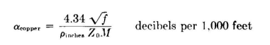
These equations are restricted to cases of complete symmetry of currents in the feeder cross section and to those configurations which give equal division of current among the high-potential wires and the grounded wires. The constant is derived for hard-drawn copper. Also, all wires must have the same radius. For applications where open-wire unbalanced feeders are used, the total attenuation is simply the sum of the above two equations, plus some small estimated additional allowance for insulation loss. Balanced feeders, which are used almost exclusively at the high frequencies, also have two major loss components - copper loss and insular tion-leakage loss. The latter is proportional to the characteristic impedance of the system but is otherwise empirical. The loss due to heating of the copper is predictable from the equation
where M is the number of wires in parallel on each side of the circuit provided that the current is equally divided among the M conductors. McLean and Bolt31 have made measurements on two-wire and four-wire balanced lines for high-power high-frequency transmission and have found that, for a 550-ohm two-wire line, the insulation and other losses are about 70 percent of the copper loss, and for a 320-ohm four-wire line the figure is about 22 percent. at 20 megacycles. These figures provide a basis for estimating the total attenuation of feeders within this impedance range, when the copper conductors are of the order of 0.200 inch diameter.
 , whereas for copper loss only αcopper = 0.0916. These measurements show insulation and other losses to be 66 percent of the calculated copper loss. , whereas for copper loss only αcopper = 0.0916. These measurements show insulation and other losses to be 66 percent of the calculated copper loss.
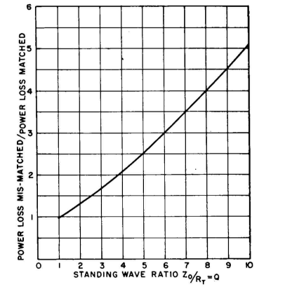
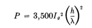
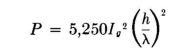
The increase in attenuation as the standing-wave ratio departs from unity is shown in Fig. 4.1. A feeder carrying a current I, terminated in its characteristic impedance and having a ground-return current Ig = I(1 - k) amperes, will radiate a small amount of power, the amount being determined from the following equations:28 For a feeder one-half wavelength long at a height h above ground, the radiated power P in watts is
and for a feeder one wavelength long
One of the causes of radiation from an open-wire line is radiation from the vertical connections at the ends. This can be reduced by decreasing the height of the line; but this in turn increases the ground-return current, which partially offsets the decrease in height. In order to use small heights and retain small relative values of ground-return current, it is necessary to use better shielding of the high-potential wires by using a greater number of grounded wires and perhaps also a smaller line cross section. The various equations for unbalanced open-wire feeders show that k must be made as near to unity as feasible, which will minimize the ground-return component 1-k. The desired properties can, in most cases, be obtained with open-wire lines, thus making it unnecessary to employ concentric lines to avoid radiation troubles. Whatever radiation occurs from the line will be horizontally polarized at right angles to it and vertically polarized in the direction of the line. The vertically polarized component is the only one likely to cause difficulty, and it can be avoided by running the lines at right angles to the direction of the critical pattern null whenever possible. The precautions taken to avoid end radiation will also aid in suppressing line radiation. Considered application of the various types of lines for which design equations are given, together with the use of still other types that may be developed using more wires, can take care of almost any situation that one is likely to encounter in practice. By a suitable choice of h and k, radiation can be reduced to any extent desired. The radiation pattern of a terminated feeder follows those of traveling-wave systems, which were discussed in Chap. 3.
|
||||||||||||||||||||||
| Home Radio-frequency Transmission Lines Useful Transmission-line Configurations Introduction |
|
|||||||||||||||||||||
Last Update: 2011-03-19