| Radio Antenna Engineering is a free introductory textbook on radio antennas and their applications. See the editorial for more information.... |

|
Home  Radio-frequency Transmission Lines Useful Transmission-line Configurations Unbalanced Feeder of the Corner Type Radio-frequency Transmission Lines Useful Transmission-line Configurations Unbalanced Feeder of the Corner Type |
||||||||||||||||||||||||


|
  |
|||||||||||||||||||||||
|
Unbalanced Feeder of the Corner TypeAuthor: Edmund A. Laport Type XIII (Fig. 4.17), using a 90-degree corner, forms, with its images, one quadrant of the field of a feeder of the cross-connected four-wire balanced type XVIII. When the metallic corner is of sufficiently large width to collect a very high percentage of the electric flux from the high-potential conductor located inside it and on its bisector line, it approaches very closely a sector of the analogous balanced prototype line, but with two adjacent zero-potential surfaces replaced by metallic sheets. There results from this principle the possibility of a line with very high power capacity that may be a good substitute for large concentric feeders.
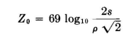
One method of constructing a corner-type line is that shown in Fig. 4.18, where economy is achieved by a simple but substantial structure. Post insulators for the high-potential conductor may not be required at as frequent spacings as for the sheet-metal corner. Longitudinal angle members between support poles, in addition to the one at the ridge, make a solid framework for the entire length of the line and maintain a neat and uniform appearance. When h > > > s and w >> s,
When h is small,
where h0 = h in the figure, h1 = h + s
There arises the question of the minimum permissible width w of the corner sheets in order to conform to the principle that the image charges on the sheets be essentially those of infinite sheets. The greatest charge concentration will be on the surfaces nearest the high-potential conductor and will taper off to zero at infinity. In fact, the rate of decrease of the charge (or the current density) as the distance from this nearest point on the sheet is increased is very rapid in many practical cases. The larger the radius p of the high-potential conductor and the smaller the value of s, the greater is the charge concentration on the sheets near the conductor and the more rapid the decay in value with distance.
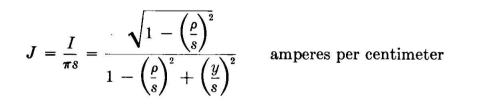
The following equation1 provides the solution of the current density J in the sheet as a function of the distance y from the projection of the axis of the high-potential conductor on the sheet:
in which I is the current in amperes in the high-potential conductor and p and s are the same values used in the equation for the characteristic impedance. A plot of J as a function of y will yield the information that will permit the designer to judge an acceptable minimum current density and thus choose the minimum sheet width w. All the geometrical dimensions are of course in the same units.
|
||||||||||||||||||||||||
| Home Radio-frequency Transmission Lines Useful Transmission-line Configurations Unbalanced Feeder of the Corner Type |
|
|||||||||||||||||||||||
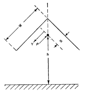
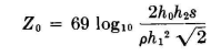
 , and h2 = h + 2s
Last Update: 2011-03-19